So, what I wonder now is how/if I can apply this to the snubber arrangement I've left on the PCB
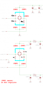
I think there's a pretty good chance that you can use the same PCB holes and the same PCB pads, to make the Quasimodo-preferred 2C+1R snubber, instead of your earlier 4C+4R design. You simply re-purpose some of the component footprints, and install a couple of insulated jumper wires (shown in boldface blue, below):
Attachments
Last edited:
That's great, I can give that a try! Am I right in thinking the snubber should be near to the diode bridge or in fact is it better closest to the transformer anyhow?
Yikes! Only now do I see that your second schematic uses a center tapped transformer. For that case you need two CRC snubbers, please see the bottom row of QM design note page 11, and subsequent discussion. The bottom half of Post #341 incorrectly includes only a single snubber. Oops. You need two, not one.
You want to locate your snubbing components Cx, Cs, and Rs as physically close to the transformer secondary as possible -- right at the ends of the transformer lead wires -- to minimize loop area, and to snub out oscillatory ringing immediately. Someone asked that same question previously in this thread, and someone else answered, but I don't have time to search for it.
You want to locate your snubbing components Cx, Cs, and Rs as physically close to the transformer secondary as possible -- right at the ends of the transformer lead wires -- to minimize loop area, and to snub out oscillatory ringing immediately. Someone asked that same question previously in this thread, and someone else answered, but I don't have time to search for it.
Thanks! Yep, that 12V CT will need two, I measured it in accordance with the PDF which shows two 3 component snubbers. If they are best located near the transformer then I shall simply add them to the not-yet-designed transformer board, as you suggest, right on the transformer output.
As for the PSU board, I can simply leave these parts unpopulated.
As for the PSU board, I can simply leave these parts unpopulated.
PCB and/or parts
Have boards made by OSHPark and/or parts in stock as per my earlier post. $16 for a PCB and $45 for complete kit free shipping to the lower states. The standard BOM except 0.1% resistors.
Have boards made by OSHPark and/or parts in stock as per my earlier post. $16 for a PCB and $45 for complete kit free shipping to the lower states. The standard BOM except 0.1% resistors.
I bought the kit from "dsolodov", it works just fine. The parts came in a labeled plastic bags, it was a cinch to put together.
I too wondered why 0.1% R's, there is no reason for this degree of precision R, in this application, but they also do not hurt either.
Well done Mark Johnson, thanks!!
Rick Savas
I too wondered why 0.1% R's, there is no reason for this degree of precision R, in this application, but they also do not hurt either.
Well done Mark Johnson, thanks!!
Rick Savas
I added a switch to externally measure the pot value - it saves removing the 'trim pot' to measure value - makes the testing very simple.
I was thinking about adding a resistance display to the tester (like a multimeter) but as it's not a daily use device ....
I was thinking about adding a resistance display to the tester (like a multimeter) but as it's not a daily use device ....
I added a switch to externally measure the pot value - it saves removing the 'trim pot' to measure value - makes the testing very simple.
If you connect the Rs, Cs network with Cs to the Quasimodo output pin (transformer secondary) and Rs to ground ...
Then Rs is DC isolated from the rest of the circuit. You can measure Rs with your ohmmeter without removing it from its socket.
Last edited:
Aah, right! Didn't see that, Mark - thanks
Everybody interested in 'better power supply sound' should use one of these gadjets
Everybody interested in 'better power supply sound' should use one of these gadjets
Tried the Quasimodo with several Nuvotem xformers, all 230 primary with 15V-0-15V secondaries:
Here are the results for critical damping (15V out paralell, first 2 figures) -
For a 120VA xformer, C1= 0.01u, C2 =0.15u, R1 ~42.5 ohm
For a 80VA xformer, C1= 0.01u, C2 =0.15u, R1 ~39 ohm
For a 50VA xformer, C1= 0.01u, C2 =0.15u, R1 ~38.6 ohm
However, I cannot measure the value for with only one 15V out while the other 15V shorted (last figure):
Attachments

I suppose you could connect up the transformer in a crazy & unrealistic configuration, and use Quasimodo to find an "Rs_Phony" for the secondary from end-to-end (with center tap floating). Then make a tenuous assumption that the correct value of Rs to use in each of your two snubbers (from each end to center tap) is probably something in the neighborhood (1/2)*Rs_Phony.
You may decide "hey, it's better than nothing."
You could try it in simulation to see whether the assumption is bogus or not.
You may decide "hey, it's better than nothing."
You could try it in simulation to see whether the assumption is bogus or not.
Hi Mark congratulation for this excellent job!
- Insert and solder all resistors, Schottky diodes, and 0.1uF ceramic bypass caps (photo 1)
- Insert and solder the two 8-pin ICs, the DIPswitch, and the power-on LED (photo 2)
- Insert and solder the MOSFET, the film capacitors, and the electrolytic caps (photo 3)
- Insert and solder the green terminal block, the 3-pin socket for RV1, the (4x2 + 3x2) sockets for C2 and C3, and the six 1-pin headers for +VIN, SCOPE, and GND (photo 4)
Is it possible post this through hole version pcb in pdf format?
Thanks.
I received an email from DigiKey this morning (attached), warning me that the SO8 surface mounted MOSFET used in Quasimodo v3, is now considered Obsolete.
DigiKey USA says they still have 1900 of them in stock (part number 497-12346-1-ND), priced at USD 0.75 for qty=1, or USD 0.294 per piece if you buy qty=1000.
I checked the other two SO8 MOSFETs, listed as acceptable substitutes on the Quasimodo v3 Bill Of Materials, and both are in stock at DigiKey. I also checked the manufacturer's website, both of these parts' listings say: "Status: Active and Preferred".
Attachments

I still have several boards and/or full part kits in stock.
How do I buy a board and kit?
Jim
I still have several boards and/or full part kits in stock.
Do you have full kit SMD parts?
How do I buy a board and kit?
Jim
I have PM'ed you about this.
Thanks
Jim
FYI, when I sold off my excess inventory at my cost, these were the prices (including shipping). You can click the little arrowheads at top right of the quotation boxes to see the original posts.
I sourced all parts from DigiKey and all PCBs from Seeed Studio. Others may source parts and PCBs from different distributors or PCBfabs, and so their prices may be lower. (DigiKey is notorious for high prices!)
I'm all sold out and have no more extra v.3s and/or v.4s to sell or to give away. None.
I sourced all parts from DigiKey and all PCBs from Seeed Studio. Others may source parts and PCBs from different distributors or PCBfabs, and so their prices may be lower. (DigiKey is notorious for high prices!)
I'm all sold out and have no more extra v.3s and/or v.4s to sell or to give away. None.
v.3 (surface mount)
PCB + full kit of all parts: {USA: $11.00} {MEX,CAN: $16.00} {rest of world: $22.00}
v.4 (thru hole)
PCB + kit of all parts: $18 {USA}, $20 {CAN, MEX}, $26 {rest of world}
![WP_20140908_001[1].jpg](/community/data/attachments/406/406181-2ec78f439d4b0cfc0c77101b38607634.jpg?hash=LsePQ51LDP)
![WP_20140908_002[1].jpg](/community/data/attachments/406/406192-cf04bf3defdaead93bff3fdf09daa187.jpg?hash=zwS_Pe_a6t)
- Home
- Amplifiers
- Power Supplies
- Simple, no-math transformer snubber using Quasimodo test-jig