Yeah, hurried typo on my part, I had the parts the way you intended. Fixed in my post now, thanks.
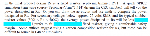
What wattage for the resistor Rs?
What wattage for the resistor Rs?
Use the design note, Luke. Find this paragraph on page 7:What wattage for the resistor Rs?
Attachments
Thanks Mark, all sorted out. I was mistaken in thinking that PDF was just the pictures on that post. Great to read and strive to understand.
I also read about using the Epcos caps and carbon comp resistors. They had one 160R and 180R, I got some of each and try and find the 2 closest to 170r. I did find a metal film at 169R to fall back on.
Altogether a good and fun learning experience, you have my gratitude!
I also read about using the Epcos caps and carbon comp resistors. They had one 160R and 180R, I got some of each and try and find the 2 closest to 170r. I did find a metal film at 169R to fall back on.
Altogether a good and fun learning experience, you have my gratitude!
Transformer - Antek AN-5218
Rs = 170R for my transformer
{my supplier of carbon composition resistors} had one 160R and 180R, I got some of each and try and find the 2 closest to 170R. I did find a metal film at 169R to fall back on.!
Why not remove the potentiometer from your Quasimodo board, connect it to the most accurate ohmmeter in your lab, set it to exactly 160.00 ohms, put it back in Quasimodo, drive your transformer, look at the waveform, and ask yourself: "Can I live with this?" If 170R gives critical damping (zeta=1.000), then 160R will give zeta=1.063. Can you live with that?
Why not do a second experiment, in which you remove the potentiometer from the board, connect it to the most accurate ohmmeter in your lab, set it to exactly 180.00 ohms, put it back in Quasimodo, look at the waveform, and ask yourself: "Can I live with this?" If 170R gives critical damping (zeta=1.000), then 180R will give zeta=0.944. Can you live with that?
You could command your Rigol oscilloscope to capture the three waveform datasets (Rs = 160R, 170R, 180R) as .CSV files, then use Microsoft Excel to plot them all on the same graph. Just like Fig.10 on page 8 of the Quasimodo design note. Are they vastly different? Are they mostly the same?
It would be pleasant to assign this homework problem to a roomful of squirming students: Plot the step response of a second order linear system, at these three values of the damping factor zeta: 0.944, 1.000, 1.063. You could do it with calculus, or with LTSPICE, or GNUPLOT, or a number of other contrivances. Are the three step response waveforms vastly different? Are they mostly the same?
Current status isWhat is the current status of a Quasimodo PCB run? I would love to have one. 🙂
- Mark Johnson: sold out of V3 (SMD), sold out of V4 (thru-hole); no plans to sell more
- gazzagazza: has blank PCBs to sell: V4 (thru-hole)
- tjencks: thinking about organizing a Group Buy in Jan or Feb 2014; send him a PM to express your enthusiasm
I have seen that in +&- power supplies that use a FWB with a center tap there is far less ringing than in a supply that does not use a center tap. Anyone else seen this? By having the filter caps connected to the center tap, could this somehow dampen the secondary? I can't directly see how, but something is going on.
Have you compared to a circuit using two bridges, and not connecting common ground until near the load?
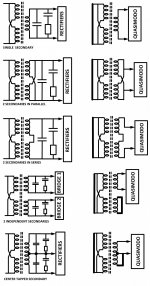
Since a center tapped transformer requires two snubbers, I recommend capturing the (damped) oscillatory waveform between secondary-1 and centertap on scope-channel-1, and also capturing the oscillatory waveform between secondary-2 and centeertap on scope-channel-2. See the discussion on pages 11-12 of the Quasimodo design note, including Figure 13 (attached below).
Attachments
When I look at the secondary without any caps or resistors I see very little ringing, then when I install one .01 cap from the top leg to the center tap and one from the bottom leg to the center tap, I still don't see the ringing that I see on a transformer without a center tap. This is all before installing the Cs Rs series snubber. On a transformer without a center tap as soon as I install a .01 alone across the secondary I see the ringing waveform clearly, but in a center tapped transformer I do not see this same ringing. I am thinking that the filter caps connected to the center tap have something to do with this, but they should not affect the secondary ringing as they are on the other side of the bridge. This is very interesting.
When I look at the secondary without any caps or resistors I see very little ringing, then when I install one .01 cap from the top leg to the center tap and one from the bottom leg to the center tap, I still don't see the ringing that I see on a transformer without a center tap. This is all before installing the Cs Rs series snubber. On a transformer without a center tap as soon as I install a .01 alone across the secondary I see the ringing waveform clearly, but in a center tapped transformer I do not see this same ringing. I am thinking that the filter caps connected to the center tap have something to do with this, but they should not affect the secondary ringing as they are on the other side of the bridge. This is very interesting.
The sides are out of phase with each other.
The sides are out of phase with each other.
How would that dampen the ringing? I measured one side at a time.
If you have the caps on both sides the ringing will be out of phase on each side but still coupled. Also when you look at the entire primary you will have 4 times the inductance of each half. So Fr will be lower.
I have managed to get a PCB, thank you Gary, and I found a source for the driver, but the transistor is not easy to source.
I have IRF610, IRFP240 and FQP3N30 in stock, would any of these be ok for the circuit ?
Best regards
Arthur.
I have IRF610, IRFP240 and FQP3N30 in stock, would any of these be ok for the circuit ?
Best regards
Arthur.
Although I'm not able to read the Danish language, I checked dk.farnell.com and it appears to me that both of the substitute MOSFETs listed in the Quasimodo V4 Bill Of Materials ("BOM" , post #58) are in stock. The I-PAK device is on the shelf, and Farnell suggests 4 different substitute devices for the TO-220 device, three of which are on the shelf. I checked their specifications and I agree with Farnell; all four of those MOSFETs will work just fine in Quasimodo thru-hole.I have managed to get a [thru hole Quasimodo V4] PCB, thank you Gary, and I found a source for the driver, but the transistor is not easy to source.
I have IRF610, IRFP240 and FQP3N30 in stock, would any of these be ok for the circuit ?
If you're unable or unwilling to buy from dk.farnell.com, here are the required properties of the MOSFET (as discussed on p.4 and p.22 of the Quasimodo design note), which you can use to help you choose a device from your favorite distributor:
- package: TO-220 or IPAK, pinout GDS (left to right)
- VDSmax > 20V
- VGSmax > 17V
- IDSmax > 2A
- Logic Level Gate preferred but not absolutely mandatory, see p.4
- RDS(on) as low as possible. RDS(on) < 100 milliohms mandatory, but < 10 milliohms preferred
-- Mark Johnson
Attachments

Last edited:
Thank you Mark,
I have read the whole thread, but have overlooked the BOM. Thank you for your patience 🙂
I will deal with everybody, but the problem is that Mouser, Digi-Key ... DK, only have an office in the Nordics, but the goods are sent from US, and our authorities are very creative when it comes to adding expenses. Last time I got components from Mouser, it took only 3 days, but I paid double for tax and other expenses, than for the components.
So buying from EU is much less expensive, but I did find an IRL transistor that should fit the bill.
Best regards
Arthur.
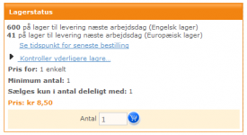
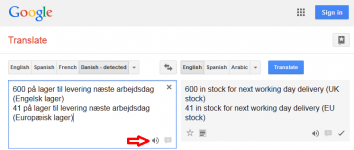
I guess they succeeded in deceiving me. When they said 41 pieces in EU stock available for next day delivery, I interpreted that to mean the parts were physically in Europe, thus not subject to USA import tariffs. Sneaky little buggers! Glad to know the list of requirements helped you find a similar, workalike part without hidden fees and delays.
(By the way, clicking the "say it for me" icon gave a nice surprise. The Danish word "lager" was not pronounced anything like an English speaker would ever guess!)
(By the way, clicking the "say it for me" icon gave a nice surprise. The Danish word "lager" was not pronounced anything like an English speaker would ever guess!)
Attachments
Last edited:
Ok, exactly on this part they claim English and European stock. But I still have an open order at Reichelt in Germany, so I can get it from there.
I like lager, but in Danish that is stock 🙂
I very much appreciate that you learnt us that snubbers are not just damping of the diode itself, which I thought before reading your paper.
I am not young, but I learn a lot being here.
I like lager, but in Danish that is stock 🙂
I very much appreciate that you learnt us that snubbers are not just damping of the diode itself, which I thought before reading your paper.
I am not young, but I learn a lot being here.
Very helpful contribution Mark!!
Gotta hand it to you, knowing your diff equ stuff, I just don't have the brain capacity/capability for it.
I wish I managed to get through the Hugh Skilling Network book, back in school, but it remains as good as new.
Will have to stick with simple algebra and ohms law 🙂 or with my new hobby, writing code for my radio/ media player project.
Thx
Rick
- Home
- Amplifiers
- Power Supplies
- Simple, no-math transformer snubber using Quasimodo test-jig