Borge, thank you for this contribution! The extra columns in your modified BOM, showing part-numbers at Mouser, will help lots of people. Thanks also for adding your remarks in column "L", they drew immediate attention to row #7 (electrolytic capacitor, 220uF).
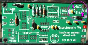
The QMV4 original BOM called for 5mm lead spacing and 8mm case diameter on these 220uF capacitors. Your Mouser part number has a 10mm case diameter instead, and I worry that it might be a very tight fit. In particular, capacitor C14 might collide with neighboring components, see photo below.
Please let us know whether you are successfully able to cram the big capacitor into that small space, and whether it solders easily. If not, then perhaps one of these other Mouser capacitors (5mm lead spacing, 8mm case diameter) might work instead:
Panasonic ECA-1VHG221B
Panasonic EEU-FM1V221B
Kemet EST227M035AG4AA
Mark Johnson
Attachments
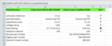
Why don't you fill out a spreadsheet, perhaps similar to the one pictured below.
Each component in the BOM has several important properties (voltage rating, package type, power dissipation rating, lead spacing, component footprint, etc.) and each of those properties is listed in the spreadsheet twice: first, the value specified in the Quasimodo V4 BOM (column B); second, the value in your proposed BOM (column C).
If they match, you get a check-mark in the OK?? column. If they don't match, you get an X in the OK?? column.
When you've got a spreadsheet that shows every single component in the QM V4 BOM, and whose OK?? column shows all check-marks (with zero X's), post it here as an aid to other diyAudio readers.
It will take effort to create this spreadsheet; it will be hard work. You will learn and grow from performing this work. I will not do it for you. If someone else volunteers to do this work for you, they are, in my opinion, robbing you of your education as a board designer.
Attachments
Hi guys,
I just placed an order on OSH Park with the very kindly provided files from post #58.
3 boards for $35 with shipping included is great! I plan to populate two of them for myself and a friend.
For your convenience I have re-attached the same zip file and added Mouser order codes to the BOM.
Thanks for your great work!
Borge
Hi Borge
Do I understand you've got a PCB left ?
If not, maybe I'll order one batch too and sell remaining PCB.
Thank you for this thread and informations 🙂
Regards
Phil
Last edited:
Hi Phil,
I will have a leftover board. But I won't promise it away before I have two assembled and working units in my hand.
Pity about the Ø10mm cap, I'll let you know how it fits when I get started on the soldering.
Børge
I will have a leftover board. But I won't promise it away before I have two assembled and working units in my hand.
Pity about the Ø10mm cap, I'll let you know how it fits when I get started on the soldering.
Børge

I'll take one. Please let me know the cost, including postage to Connecticut, USA.
Best regards,
George
Best regards,
George
Price is 4€/per board + postage. 2 boards left
GOR3: OK, will ask about postage and send you PM.
If anyone is interested, please send me PM.
GOR3: OK, will ask about postage and send you PM.
If anyone is interested, please send me PM.
Price is 4€/per board + postage. 2 boards left
GOR3: OK, will ask about postage and send you PM.
If anyone is interested, please send me PM.
YHPM
english translation please.
Hi AndrewT my own google head guess "SEARCH = YOU HAVE PRIVATE MESSAGE" 😛
I have 3 spare boards, Quasimodo V3, SMD version.
Will give them away for small compensation, to cover manufacturing expenses.
PM Sent.. 😀
Hi, I'm a newbie in DIY and starting my first project to build a linear power supply. The rectifier section of the circuit is displayed below.

I'm planning on adding a CRC snubber as per the method here, and is printing a few PCBs with Seeed to build the Quasimodo jig. I would like to ask a few questions though:
1. After adding the CRC snubber, do I still need to keep the 4 x 220pF across each individual diodes. I'm wondering if they serve some other purposes.
2. An audiophile friend of mine strongly recommends the exotic CREE diodes, do they really make a difference in a design with a proper snubber.
3. I have a few spare IRLZ24N, per post #175 it meets most of the requirement except VGSmax is only 16V (instead of 17V). If I'm only going to use 12V or below to power the Quisamodo, would the IRLZ24N will an acceptable replacement for the NTD4906N.
Thanks and regards.
Remove the Capacitors across the diodes.
The Capacitors are NOT Snubbers.
Read this thread.
It explains that resistors are Snubbers.
The Capacitors are NOT Snubbers.
Read this thread.
It explains that resistors are Snubbers.
The purpose of the caps across the diodes is to couple mains noise into your internal ground! I too had them in my earlyer linear supplies and was adviced to take them out.
I will shortly start experimenting with a differential-mode choke between the bridge and the first large cap. See
http://www.murata.com/products/emicon_fun/emc_111028_en_3.png
http://www.butlerwinding.com/client_images/catalog19973/pages/images/common mode choke/Common1.gif
The purpose of the DMC is to block AC current and pass DC current. It is a common feature in some switched supplies. See T2 of
http://cds.linear.com/docs/en/demo-board-schematic/230abcdsh.pdf
Børge
Børge
Cwtim01, have you read the Quasimodo design note (attached to post #1)? To optimize a transformer snubber using a bellringer test-jig like Quasimodo, you will need an oscilloscope. Usually people who call themselves newbies, don't own an oscilloscope yet.
If your first project is an AC-input, DC-output, lab bench power supply (i.e. not an amplifier or preamp or linestage or phonostage or other audio processing unit), then I think you can save a lot of money by purchasing plain ordinary silicon diodes instead of the more exotic silicon carbide schottky diodes from Cree or Rohm or GeneSiC. Ask your friend who strongly recommends silicon carbide diodes, how will the sonic benefits of silicon carbide be manifested in a lab bench supply?
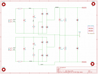
As it turns out, I built a lab bench power supply myself recently. It used an 80VA split bobbin transformer (Triad VPS36-2200), and gave a variable ±0 to ±20V output at 1.5 amps (dual tracking). The page of the schematics with the snubbers and rectifier diodes is attached below.
This transformer has two independent secondaries, and I gave each one its own snubber and bridge rectifier. Diodes were inexpensive silicon "FES-8GT" types (link 1) ; (link 2) ; (link 3) . I had a bunch of them in my parts bin when I started the design. Today I have a lot of Fairchild soft recovery diodes in my bin and I'd use those if I built another lab supply.
You can see that I used the Quasimodo recommended starting point for snubber capacitor values (Cx = 0.01uF ; Cs = 0.15uF) and that the optimum value of snubber resistor (zeta = 1.00) for this transformer, happens to be 100 ohms according to Quasimodo testing.
If your first project is an AC-input, DC-output, lab bench power supply (i.e. not an amplifier or preamp or linestage or phonostage or other audio processing unit), then I think you can save a lot of money by purchasing plain ordinary silicon diodes instead of the more exotic silicon carbide schottky diodes from Cree or Rohm or GeneSiC. Ask your friend who strongly recommends silicon carbide diodes, how will the sonic benefits of silicon carbide be manifested in a lab bench supply?
As it turns out, I built a lab bench power supply myself recently. It used an 80VA split bobbin transformer (Triad VPS36-2200), and gave a variable ±0 to ±20V output at 1.5 amps (dual tracking). The page of the schematics with the snubbers and rectifier diodes is attached below.
This transformer has two independent secondaries, and I gave each one its own snubber and bridge rectifier. Diodes were inexpensive silicon "FES-8GT" types (link 1) ; (link 2) ; (link 3) . I had a bunch of them in my parts bin when I started the design. Today I have a lot of Fairchild soft recovery diodes in my bin and I'd use those if I built another lab supply.
You can see that I used the Quasimodo recommended starting point for snubber capacitor values (Cx = 0.01uF ; Cs = 0.15uF) and that the optimum value of snubber resistor (zeta = 1.00) for this transformer, happens to be 100 ohms according to Quasimodo testing.
Attachments
As it turns out, I built a lab bench power supply myself recently. It used an 80VA split bobbin transformer (Triad VPS36-2200), and gave a variable ±0 to ±20V output at 1.5 amps (dual tracking). The page of the schematics with the snubbers and rectifier diodes is attached below.
This transformer has two independent secondaries, and I gave each one its own snubber and bridge rectifier.
Mark,
As long as you have gone to the expense of dual bridges, etc., why not keep the ground returns from the ripple caps separated back to the bridges, and connect the grounds from the separate pos and neg sides only at the star ground on the right side?
Cwtim01, have you read the Quasimodo design note (attached to post #1)? To optimize a transformer snubber using a bellringer test-jig like Quasimodo, you will need an oscilloscope. Usually people who call themselves newbies, don't own an oscilloscope yet.
Hi Mark,
Thanks for your answers. I happen to have a cheap scope meter from China which cost only $150, it just has a single channel and 50M bandwidth, but if I refer to your design notes one channel is workable though not as clean as a two channel one.
Could you give me some hints about the MOSFET.
Thanks and regards.

If your first project is an AC-input, DC-output, lab bench power supply (i.e. not an amplifier or preamp or linestage or phonostage or other audio processing unit), then I think you can save a lot of money by purchasing plain ordinary silicon diodes instead of the more exotic silicon carbide schottky diodes from Cree or Rohm or GeneSiC. Ask your friend who strongly recommends silicon carbide diodes, how will the sonic benefits of silicon carbide be manifested in a lab bench supply?
In fact my project is about building a few LPSes for my CAS chain (ARM computer, NAS, network switch, DDC ... etc) so it's indeed for audio use, and my question is whether the CREEs are worthy of their price tag, as I have to purchase 20 diodes the cost is rather important if CREEs are used.
Thanks and regards.
- Home
- Amplifiers
- Power Supplies
- Simple, no-math transformer snubber using Quasimodo test-jig