It should have said: "Of course ommiting the input capacitor".
Maybe I have to many questions 🙂
But could the Quasimodo circuit also be used to size zobel networks for audio transformers, of ommiting the input capacitor ?
I suggest building actual circuitry with real diodes, and making careful quantitative measurements.
There's an article "Measured RFI Differences Between Rectifier Diodes in Simple Capacitor-Input Power Supplies" (The Audio Amateur, issue#1, 1994, p.26) which compared three or four diodes. The 1N400x was found to be the worst (largest amount of RFI generated) of the diodes tested. UF400x was not among them; perhaps it was not available in 1994.
An excellent reason for measuring real diodes rather than simulated ones, is found in this article from a peer-reviewed academic journal, 22 years ago: A Simple Diode Model with Reverse Recovery. Pay careful attention to the first two sentences. Fortunately, bold claims such as these can be tested; anybody with access to SPICE can apply a sinewave to a diode and plot I(t) and dI/dt for themselves. Even a diode whose SPICE model was provided by the manufacturer.
Since I wrote that article in TAA I have found new data. I place a .1uf stacked film cap across the secondary of the transformer and it gets rid of the RFI that I can measure. You don't need a resistor in series with the cap, but you could put a small value of .5-2 ohms with it. A simple test of the results is to place a battery powered AM radio next to the power transformer and listen for buzz with, and without the cap. I have also used a Tektronix spectrum analyzer to measure the RFI from the power supply and it shows the same result as the AM radio. Try the radio, and you will hear it for yourself, its a real easy way to check for RFI.
Good info, thank you......I place a .1uf stacked film cap across the secondary of the transformer and it gets rid of the RFI that I can measure. You don't need a resistor in series with the cap, but you could put a small value of .5-2 ohms with it.
Is there a reason for stacked film vs wound capacitor, eg PP ?.
Dan.
Mr. Miller,
thanks for the info. I believe Mark Johnson's method is superb for dealing with ringing at switch off. So I might ask you, do you suggest that the 0.1uF method takes care of that ringing (dependent on the leakage inductance) too, or extinguishes any RF a diode might generate during its normal operation?
I ask this since the diodes in the circuits you measured might not ring at all (or ringing could be extremely small).
Good info, thank you.
Is there a reason for stacked film vs wound capacitor, eg PP ?.
Dan.
Yes, the stacked film is non inductive, so it works better at hi freq. RF, but if you do not have that kind, try what you have to see the effect.
Mr. Miller,
thanks for the info. I believe Mark Johnson's method is superb for dealing with ringing at switch off. So I might ask you, do you suggest that the 0.1uF method takes care of that ringing (dependent on the leakage inductance) too, or extinguishes any RF a diode might generate during its normal operation?
I ask this since the diodes in the circuits you measured might not ring at all (or ringing could be extremely small).
Now, almost 20 years since I wrote the article, I feel that the ringing of the transformer due to the diodes turning off fast causes the most RFI. The diodes still matter, and low C, very high voltage diodes sound the best to me. I make bridges of four 1KV/2.5A diodes that have a pass thru C of 15pf each. we want as low a C as possible in series, to pass the least amount of RFI. A .1uf cap across the secondary, and one across the first filter cap shorts out the RFI from the diodes.
Please try the AM radio test on your gear if you can. Thanks.
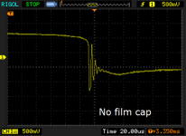
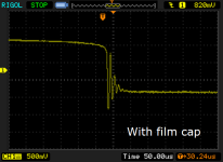
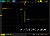
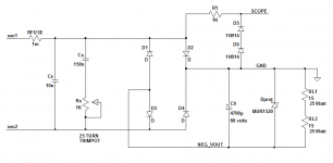
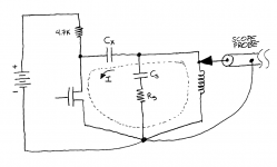
I tried that experiment myself, in August 2013. I used a test circuit adapted from Figure 16.10 in Bob Cordell's book (p.353), conceptual schematic below.Since I wrote that article in TAA I have found new data. I place a .1uf stacked film cap across the secondary of the transformer and it gets rid of the RFI that I can measure.
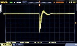
Monitoring the "Scope" node on a board with Cx removed, Rs removed, Cs removed, I got the WITHOUT waveform attached below.
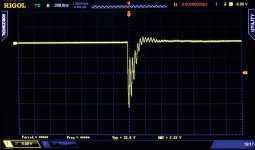
When I installed a stacked film capacitor in position Cx, but left Cs and Rs unpopulated, I got the WITH waveform attached below.
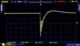
The stacked film capacitor did not eliminate the oscillatory ringing. A full CRC snubber a la Hagerman, did completely damp out all oscillation. The resistor provides a loss mechanism which destroys the Q of the resonant circuit. See the SNUBBED waveform attached below.
By the way, the annoyance and difficulty of using this particular test jig, gave birth to the Quasimodo idea. To dial-in an optimum snubber, it turns out that you don't actually need 25 watt resistors, or a (scary! possibly dangerous!) connection to the AC mains, or a big thumping $5.00 electrolytic capacitor with a 15-ampere reverse protection diode. All you need is a low-Z pulse generator, which is easily constructed on a tiny (50mm x 50mm) PCboard, running off a 9V battery. Not the scary, dangerous AC mains. Whew.
Attachments
I have looked across the secondary with my digital Tektronix scope and see a large spike when the diodes shut off when no cap is there. With the cap the spike is very reduced and at a higher freq. But the sound of the buzz on the AM radio is gone, also gone on a Tektronix spectrum analyzer.
I can tell you with 40yrs of RF work behind me that if you want to get rid of RF with a cap, the lower the R and Z in the path of the cap the better. The power transformer is not a classic case of an L with the film C across it. The transformer has the power line on one side, with all its R, C, and L. Sometimes you just have to try a theory with real parts.
If I cannot see the RFI on a spectrum analyzer, or hear it on a radio, that is good enough for me. I agree that classic snubbers have there place, but with our transformer power supplies a cap across the secondary is a simple fix that you can hear with the AM radio.
If you look at all the power line inlet filters from companies like Cor-Com, you do not see RC snubbers, just C's. If you like RC snubbers and they sound good to you, then you should use them, after all this is just a hobby.
I have looked across the secondary with my digital Tektronix scope and see a large spike when the diodes shut off when no cap is there. With the cap the spike is very reduced and at a higher freq.
Is this a typo? Do you mean lower frequency (which is what theory predicts)? Maybe you can post some WITH and WITHOUT scope photos similar to the photos in post #127?
The power transformer is not a classic case of an L with the film C across it. The transformer has the power line on one side, with all its R, C, and L. Sometimes you just have to try a theory with real parts.
I agree and indeed that's exactly what I did. AC mains -> power transformer primary -> power transformer secondary (nodes "sec1" and "sec2" on schematic) -> diode bridge -> 4700uF filter capacitor -> load resistor. Scope is across bridge diode D2. When I tried your theory with real parts, the theory failed: connecting a film capacitor across the transformer secondary did not remove RFI.However, when I tried classical circuit theory (second order linear systems), again using real parts, it succeeded. Connecting a damping resistor across the transformer secondary gave measured results that match theoretical predictions: critical damping (zeta = 1.0) removed RFI.
It's worth mentioning that the capacitor you advocate is the first 1/3rd of the "CRC snubber" that I prefer. Your capacitor across the transformer secondary is "Cx" in a Hagerman/Quasimodo snubber. There is also a Cs,Rs network across the secondary, in which Rs provides the dissipation that annihilates the Q of the secondary. That's what removes RFI at least in classical circuit theory.
As I recall, you found that your spectrum analyzer wasn't able to reliably measure diode RFI even when no film capacitor was connected across the transformer secondary. Here's the passage:
After probing around I started to see some activity in the 10kHz-2MHz range, but the analyzer did not have enough gain to view it clearly. I then built a 20dB preamp using an Analog Devices AD811. ... With the added gain of the preamp, I was able to see a series of narrow pulses on the output of the rectifier bridge with the spectrum analyzer.
Perhaps this explains why the capacitor-across-the-secondary appears to eliminate RFI in your testing: Perhaps your measurement technique simply isn't sensitive enough. You connect the spectrum analyzer across the power supply's 1000uF filter capacitor; the better this capacitor does is job, the smaller is the input signal to your analyzer. Even though your Tek 2710's dynamic range goes all the way down to (2.5 microvolts into 50 ohms), i.e., -129dBm, you required an external preamp to see the signal. You're hunting for ~ 2.5 microvolts even before the capacitor-across-the-secondary. No wonder it's possible for this signal to disappear. Anything that attenuates the amplitude by a factor bigger than the preamp's gain, renders RFI invisible. Maybe your film-capacitor-across-the-secondary does just that. I don't have a good estimate of the quantitative relationship between diode current, radiated RF power, and transistor radio input sensitivity; maybe its sensitivity is no better than the Tek spectrum analyzer's. (Or maybe it's LOTS better; I simply don't know).Maybe Cordell's measurement technique, which zeroes in upon the voltage across the rectifier diode rather than the (filtered) output voltage, is much more sensitive. The amplitude of the oscillatory waveforms in Post #127 is about 1500 millivolts peak to peak; that's more than a hundred thousand times greater than the 2.5 microvolt signal at the spectrum analyzer input.
Last edited:
I do not have a way to post photos. In my TAA article I was measuring after the bridge, now I am measuring before the whole power supply as it is throwing out RF
I have connected just a 100 ohm resistor across the secondary, no .1uf, just a big 100 ohm resistor and I can hear buzz and see it on the analyzer. The analyzer is coupled with a coil of wire as an antenna, so it is truly looking at RFI, like the radio is. Radiated emissions are far weaker that the conducted emissions, so if I can hear it on the radio, the RFI is much higher on the wiring of the power supply.
If you or anyone else just tries the radio test you will hear what I mean. Your CRC filter might be needed to reduce RFI to its lowest point, or just a .1uf cap might be all that is needed. I, like my friend John Curl, like simple and elegant solutions. In Johns Parasound phono preamp he places a large film cap right across the AC input line with no R. The final test is how does it sound? Does a C or a CRC sound better? This is really all that matters isn't it?
I forgot to say in my above post, that I cannot believe that adding the .1uf film in you photo did not change the waveform. Photo 2 looks like a copy of photo 1. The cap had to do something, good or bad.
I know how the radio would sound after the cap was added. :^)
I know how the radio would sound after the cap was added. :^)
Hmmm, Morgan Jones's article on rectifier snubbers (Linear Audio v.5) measured the secondary leakage inductance of several transformers. The measured values varied from a low of 61 uH (Figure 4) to a high of 595uH (Figure 7). To add one more datapoint, I measured the Avel Lindberg toroid in my 50W+50W Akitika power amp and found its secondary leakage inductance was 240 uH.
When we put a Rick Miller 0.1uF capacitor across the secondary of each of these transformers, what is the resonant frequency?
Since the "AM radio" band in the USA extends from 530 kHz to 1610 kHz, it's not surprising that an AM radio receiver cannot detect any RFI from these transformer+capacitor circuits. They are resonating like crazy, but the radio is tuned to the wrong frequency: off by a factor of 8X! Good idea, wrong measuring instrument.
I'm surprised that your friend John Curl never performed this calculation.
When we put a Rick Miller 0.1uF capacitor across the secondary of each of these transformers, what is the resonant frequency?
- 61uH || 100nF resonates at 64.4 kHz
- 240uH || 100nF resonates at 32.5 kHz
- 595uH || 100nF resonates at 20.6 kHz
Since the "AM radio" band in the USA extends from 530 kHz to 1610 kHz, it's not surprising that an AM radio receiver cannot detect any RFI from these transformer+capacitor circuits. They are resonating like crazy, but the radio is tuned to the wrong frequency: off by a factor of 8X! Good idea, wrong measuring instrument.
I'm surprised that your friend John Curl never performed this calculation.
I think we all know that John knows what he is doing, that is how he gets his class "A" reviews in the mags.
Harmonics and mixing products can and do extend higher into the AM band. A diode is the best mixer and we have four of them.
You can do all the math you want but in the real life power supply things are not always as calculated.
Now the BIG question, at what level is RFI affecting our sound enjoyment? If it is below a certain point does it still matter? How it sounds is ALL that matters.
post127 confirms what I posted in the other Thread.
The RESISTOR is the snubbing device that absorbs the oscillation energy.
The RESISTOR is the snubbing device that absorbs the oscillation energy.
More than a 1000 words 🙂 left to right 4, 8 and 15 Ohm, 10nF directly parallel to the transformer and 100nF in series to with resistor.
Attachments
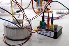
P.s. (to the above) the question is, although I did dampen one frequency (in the middle picture), there is the other (higher) frequency. Any suggestions?
Now the BIG question, at what level is RFI affecting our sound enjoyment? If it is below a certain point does it still matter? How it sounds is ALL that matters.
If one suggests that installing an CRC filter might alter the sound in a bad way, or actually in a way worse than just using a 100nF cap, I might also suggest that every known audio practice we apply to power or preamp stages lacks essence - if these diodes could affect sound that much, it would be pointless to seek 0.001% THD figures and so on (if it isn't already for some 🙂). Because the final musical product could not be actually consistent. It would even depend on the transformer leakage, and a good desing is supposedly independent of such terms.
Of course, you don't say the above. But sometimes, some people seem to swear by it. So I close the "off-topic", and move on to the final pros and cons - that is, if there is any reason a CRC should be really more tricky.
Now, if we agree that one can't suppose that sound goes best if you omit a CRC filter (thus, not removing all RFI), I feel it is good practice to design it and include it. After all, it is cheap. And ensures that not only no RFI from ringing dissipates energy after the bridge, but also that less RFI is exposed backwards - so mains stays cleaner too, for other appliances.
At last, let me say this: I don't currently have a calibrated scope at hand, so I could call the design of a Mark Johnson CRC filter a not-so-simple task. It seems to me that you can't call the 0.1uF simple, against a CRC - you must call it overly simple. Mark's technique is awfully simple, if you've got the scope. So I can't imagine how it would be a nuisance when designing anything with a linear power supply.
I like your "simple and elegant" approach, in fact it is something I seek in audio material I am willing to read. But I think that given your expertise and equipment, it is an overkill to say this CRC design isn't just as simple and elegant. In fact, I find it more elegant, since it is guaranteed to let me sleep without having to bother about ringing again. 🙄
All the above with respect to your experience and work. 🙂
Last edited:
Yes, its the actual measurement setup that I used. The 33R is in parallel to the potentiometer that is building. A precision multimeter was used to measure the actual resistances.
FdW, I have also occasionally seen those high frequency, low amplitude wiggles. Rearranging the wiring between Quasimodo, the transformer, and the scope can help to shrink or eliminate them; you want to reduce the total length of the current loop, and to minimize unwanted (parasitic) inductance. For example, you probably want Cx to have extremely short leads.
You can also experiment with adjusting the power supply voltage that feeds Quasimodo; sometimes the cleanest waveforms are observed at the extremes of the supply range.
You can also experiment with adjusting the power supply voltage that feeds Quasimodo; sometimes the cleanest waveforms are observed at the extremes of the supply range.
Attachments
- Home
- Amplifiers
- Power Supplies
- Simple, no-math transformer snubber using Quasimodo test-jig