I'm interested in participating in the group buy. That if I read it correctly. Apologies otherwise...
$18 includes parts? I just hafta "stuff" the board & solder everything up?
I'm in! Thanks. I'll keep watching.
Tony
$18 includes parts? I just hafta "stuff" the board & solder everything up?
I'm in! Thanks. I'll keep watching.
Tony
Status update: Twelve PCBs + kits have been sold; four remain.
The most common purchasing errors have been
The most common purchasing errors have been
- Not reading the sales notice (post #89 in this thread)
- Not following the five step procedure named "How to Order"
- Not comprehending these sentences: No Bitcoin, no PayPal, and no credit cards either. Will I change my mind if you ask me another 500 times? No.
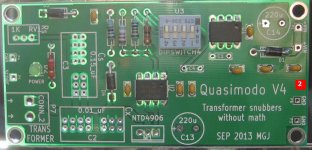
Build Guide for Quasimodo V4 thru-hole
- Insert and solder all resistors, Schottky diodes, and 0.1uF ceramic bypass caps (photo 1)
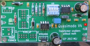
- Insert and solder the two 8-pin ICs, the DIPswitch, and the power-on LED (photo 2)
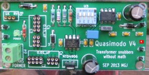
- Insert and solder the MOSFET, the film capacitors, and the electrolytic caps (photo 3)
- Insert and solder the green terminal block, the 3-pin socket for RV1, the (4x2 + 3x2) sockets for C2 and C3, and the six 1-pin headers for +VIN, SCOPE, and GND (photo 4)
Attachments

Mark
I've PM'd you to purchase a V4 kit so will have a stab at the rational for different frequencies. I have not done the math on what the frequencies are but I can see 2 reasons, firstly differing mains frequencies and secondly exploration of the mains frequency harmonics. Am I close?
I've PM'd you to purchase a V4 kit so will have a stab at the rational for different frequencies. I have not done the math on what the frequencies are but I can see 2 reasons, firstly differing mains frequencies and secondly exploration of the mains frequency harmonics. Am I close?
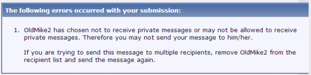
OldMike2, I attempted to send you a PM and got the peculiar error message shown below. Maybe your PM box is full, or maybe you disabled incoming Private Messages? So I sent you the QMV4 ordering information via email to your string1.string2.string3@gmail.com address.
Your theories about the frequency select switch on QMV4 do not match mine. I'm guessing that if you perform the mathematical calculations which you identified and then postponed, their results might give surprise and insight.
Your theories about the frequency select switch on QMV4 do not match mine. I'm guessing that if you perform the mathematical calculations which you identified and then postponed, their results might give surprise and insight.
Attachments
Tx Mark,
I found out I had inadvertently restricted Privat messaging, should work now. Your direct e-mail was received and I have responded.
Regards
Mike
I found out I had inadvertently restricted Privat messaging, should work now. Your direct e-mail was received and I have responded.
Regards
Mike
Just a quick thanks Mark. Now I realised I have already built a circuit like this for testing SMPS and Inductors, albeit in higher current form, but now I want to go back through some of the most directly practical maths i have seen in a long time.
So much for "No Math"
So much for "No Math"
Thanks for the kind words, whizgeek! RF folks have been using similar gear for a long time; first the Boonton Q Meter, and now the Blue Ring Tester which you can buy, brand new, today. I'm told that NMR research labs use equipment like this extensively, since inductor Q is such a crucial parameter in their experimental rigs. I won't mention Tesla coils, coil guns, stun guns, or plasma speakers except to say: they exist.
I'm not surprised to hear that SMPS folks investigate inductor S.R.F. by smacking the inductor and watching it self resonate; it's easy and it's direct - unlike indirect procedures such as extract-from-a-plot-of-impedance-vs-frequency, as in the Linear Audio article by Morgan Jones.
I'm not surprised to hear that SMPS folks investigate inductor S.R.F. by smacking the inductor and watching it self resonate; it's easy and it's direct - unlike indirect procedures such as extract-from-a-plot-of-impedance-vs-frequency, as in the Linear Audio article by Morgan Jones.
Has anybody tried the Quasimodo for tuning zobel networks for loudspeaker drivers ?.
Are there any boards or kits still available ?.
Dan.
Are there any boards or kits still available ?.
Dan.
The speaker Zobel is for a different purpose.
It is to flatten the impedance so that a passive filter will operate as modeled.
It is to flatten the impedance so that a passive filter will operate as modeled.
Status update: only one Quasimodo kit remains unsold. After it's gone, you'll need to buy from tjencks and/or gazzagazza.
If interested, please see post #89 of this thread for the five step "How To Order" procedure.
If interested, please see post #89 of this thread for the five step "How To Order" procedure.
So, can we assume that ordinary, "slow" 1N400x diodes are better (in terms of ringing) than ultra fast (but not soft recovery!!) diodes? Say UF400x?
I once performed a Spice analysis where 1N400x performed better, when I changed their tr time, making it smaller - actually turning the diode into ultra fast. Ringing was almost gone.
This is in contrast with my opening paragraph. Saying so, I assume that fast rectifiers include higher dI/dt in their circuits. I assume this because it can move its forward current from its working value to 0 faster - so, same dI, but in less dt, equals larger dI/dt. 😕
I suggest building actual circuitry with real diodes, and making careful quantitative measurements.
There's an article "Measured RFI Differences Between Rectifier Diodes in Simple Capacitor-Input Power Supplies" (The Audio Amateur, issue#1, 1994, p.26) which compared three or four diodes. The 1N400x was found to be the worst (largest amount of RFI generated) of the diodes tested. UF400x was not among them; perhaps it was not available in 1994.
An excellent reason for measuring real diodes rather than simulated ones, is found in this article from a peer-reviewed academic journal, 22 years ago: A Simple Diode Model with Reverse Recovery. Pay careful attention to the first two sentences. Fortunately, bold claims such as these can be tested; anybody with access to SPICE can apply a sinewave to a diode and plot I(t) and dI/dt for themselves. Even a diode whose SPICE model was provided by the manufacturer.
Well, certainly you have to measure everything in practice. I was just asking whether there is actually a type of diode you can safely assume that will ring less, given a cetrain property it has.
For example, you wouldn't choose a poor stability capacitor to determine your snubber value. So one says "lets buy a film, stable cap and build around it". But you can't determine which brand of cap would suit mostly inthe long term, for example.
In that manner actually - whether there are diodes to avoid. I need 48 diodes for my power supply, so I will not spend much money and space on them. Which is why I suppose that my choice will ultimately be "fast or slow". 🙂
I would recommend everybody to download the ZIP file and read the PDF paper, if you havn´t already done that. It answers pretty much every question you may have.
And then to the dip switches, I dont think anybody did repond on those yet. I suppose the dip swithes at least will be able to supply 50, 60, 100 and 120 Hz, and I think they are in the circuit to make you able to simulate single and double rectification in different mains areas.
Unfortunately I were not lucky to get the last kit.
Best regards
Arthur.
Before I read this I article I allways thought that snubber circuits where just rounding the edges of the switching noise in the bridges, which this circuit may also do.
But in that this circuit is placed before the bridge, I still think there must be some RF noise generated in the bridge - is that a correct assumption ?
And is it possible to get rid of this noise just via the power caps and som bypassing with film caps - Say for instance 22,000 uf | | 100 nf ?
Just to end the story 🙂
Best regards
Arthur.
Maybe I have to many questions 🙂
But could the Quasimodo circuit also be used to size zobel networks for audio transformers, of ommiting the input capacitor ?
But could the Quasimodo circuit also be used to size zobel networks for audio transformers, of ommiting the input capacitor ?
- Home
- Amplifiers
- Power Supplies
- Simple, no-math transformer snubber using Quasimodo test-jig