Tears of joy, I can damp a ringing transformer. Thanks to yoaudio aka Daryl for his gift and Mark for sharing his design to this community. I can start snubbing!

Congratulations dewdrop on a successful build!
I think you might have reduced Rs a little too much. You want the 2nd lumpity bumpity (trough) to just barely disappear. But in your picture it has gone past flatline and is now a weak bump upward.
Have a look at Figure 10 of the Quasimodo design note .pdf. You want the 2nd bump (trough) to progress from black, to magenta, to blue, to green, to red. When it's perfectly flat, like the red trace, stop. Don't keep cranking the knob.
How to measure using two back to back transformers? I ask because I use two R-Cores primary 230V seconday two 21V 120VA each.
Please address any questions or requests for technical support, to the diyAudio community as a whole.
I don't know about other members, but I myself have only applied Quasimodo to the five transformer configurations shown in Figure 13. If your configuration is one of those, connect shorting bars as shown.
If your configuration is NOT one of those, please provide a readable schematic diagram and please label every primary winding with a "P" and every secondary winding with an "S". If for example there are three transformers, use the names X Y and Z to label the transformers and use numbers to distinguish the different individual windings on a transformer.
Thus PX2 means primary winding #2 of transformer X.
SY1 is secondary winding #1 of transformer Y.
PZ1 is primary winding #1 of transformer Z.
This will make it crystal clear what circuit you are dealing with. I'm unable to understand what circuit the quote above is attempting to describe.
Thanks Mark for the insight, will do just that.Have a look at Figure 10 of the Quasimodo design note .pdf. You want the 2nd bump (trough) to progress from black, to magenta, to blue, to green, to red. When it's perfectly flat, like the red trace, stop. Don't keep cranking the knob.
I'm unable to understand what circuit the quote above is attempting to describe.
Used attached schematic.
Both transformers specs:
Primary 230V
Secondary dual 21V connected in parallel
Attachments

Some additional tests done today.
I noticed for one set, it was 25ohm and the other is 20ohm. Typically do we need to snub the secondary outputs individually?
I noticed for one set, it was 25ohm and the other is 20ohm. Typically do we need to snub the secondary outputs individually?
You need to do the measurement on every secondary. Be sure to short unused pair first. It got different Rs reading if one is not shorted. However, I got same Rs reading from 2 different methods illustrated below.

Will a shorted Cx or Cs be a hazard?
Should the capacitors used in the final implementation be X2 rated?
Should the capacitors used in the final implementation be X2 rated?
Thanks canvas. Will go ahead and measure the windings individually.You need to do the measurement on every secondary. Be sure to short unused pair first. It got different Rs reading if one is not shorted. However, I got same Rs reading from 2 different methods illustrated below.
View attachment 761014
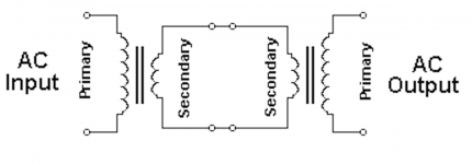
I have never tried to build audio equipment with two power transformers in series as shown in post #1605 (copied below). Nor have I ever tried to find a critical damping resistance for an arrangement like that.
I think you may have no other choice, except to invent one or two or three different ways to attach snubber(s) to this arrangement. Then find out which one works most effectively on the lab bench or in SPICE simulation. Once you know that, you can probably use Quasimodo to find snubber resistance value(s) that overdamp the system.
_
Attachments
Some additional tests done today.
I noticed for one set, it was 25ohm and the other is 20ohm. Typically do we need to snub the secondary outputs individually?
Yes you do need to snub each secondary separately. Be aware that some transformer secondaries, even though they produce the same voltage, have slightly different inductances due to one being wound over top of the other, requiring slightly different Rs values. Hammond EI power transformers are one example of this.
Take care,
Doug
I have never tried to build audio equipment with two power transformers in series as shown in post #1605 (copied below). Nor have I ever tried to find a critical damping resistance for an arrangement like that.
I think you may have no other choice, except to invent one or two or three different ways to attach snubber(s) to this arrangement. Then find out which one works most effectively on the lab bench or in SPICE simulation. Once you know that, you can probably use Quasimodo to find snubber resistance value(s) that overdamp the system.
_
Thanks for your frankness Mark.
I have never tried to build audio equipment with two power transformers in series as shown in post #1605 (copied below). Nor have I ever tried to find a critical damping resistance for an arrangement like that.
I've never tired this, but I heard this will improve the sound. For this arrangement, I think we can short the 2nd primary and measure its secondary, because the mains are also from a series of large transformers.
It acts like an isolation transformer. The question is: I snubber like usual the 1st input transformer but I snubber also the primary of the 2nd output transformer? Or I have to snubber like if was only one transformer?
Last edited:
If "please tell me the answer" doesn't succeed, then you may have no other choice except to work it out yourself, either through lab experiments or SPICE simulations or a combination of the two.
Hi FelipeOK I will take mine own way.
Why are you using this type of TX combination ?
Hi Ricardo,
To avoid a custom or new transformer for valve equipment, also heard is very good because acts as isolation transformer.
Cheers
Felipe
To avoid a custom or new transformer for valve equipment, also heard is very good because acts as isolation transformer.
Cheers
Felipe
Hello,
Tried the search feature and looked at some of the incredible number of posts on this subject. Did not find anything that indicated this article was posted here.
Anyway, for a quite different take on what snubbing is needed see:
Snubbers For PSUs
Regards,
Greg
Tried the search feature and looked at some of the incredible number of posts on this subject. Did not find anything that indicated this article was posted here.
Anyway, for a quite different take on what snubbing is needed see:
Snubbers For PSUs
Regards,
Greg
Hello starkeyg, it was linked here less than a month ago. Have a look at post #1568 and its follow ups through about #1588 or so. #1575 brings a smile.
_
_
Last edited:
- Home
- Amplifiers
- Power Supplies
- Simple, no-math transformer snubber using Quasimodo test-jig