Quasimodo kit
PM sent, @dsolodov
I have Quasimodo TH V4 kits in stock. Please PM your e-mail address for a Paypal invoice. Please note, if you are outside of the United States.
PM sent, @dsolodov
Another plus for the kits from @dsolodov. Nicely done, looking forward to building it.
And a very big thanks to Mark Johnson for sharing the design and all the knowledge. I've enjoyed this thread quite a bit.
And a very big thanks to Mark Johnson for sharing the design and all the knowledge. I've enjoyed this thread quite a bit.
Hi everyone,
I got a PM from somebody who thinks they may want to buy 16 fully assembled Quasimodo PCBs if possible, or else 16 bare PCBs. (I have neither). If you think you may be able to help this member out, PM me and I'll send you their diyAudio screenname and you can connect. They are in the Malaysia / Singapore / Indonesia part of the world.
I got a PM from somebody who thinks they may want to buy 16 fully assembled Quasimodo PCBs if possible, or else 16 bare PCBs. (I have neither). If you think you may be able to help this member out, PM me and I'll send you their diyAudio screenname and you can connect. They are in the Malaysia / Singapore / Indonesia part of the world.
jig for sale
 Hi everyone,
does someone is interessted in some Quasimodo V4 PCB kit or fully assembled?
I´ve four to sell. please PM me. preferred region Germany or EU.
Luckily I´m successfully jigged my Transformer for my next audio project and had a lot of fun. Thank you all and special Thank to Mark for all the amassing input here.
Hi everyone,does someone is interessted in some Quasimodo V4 PCB kit or fully assembled?
I´ve four to sell. please PM me. preferred region Germany or EU.
Luckily I´m successfully jigged my Transformer for my next audio project and had a lot of fun. Thank you all and special Thank to Mark for all the amassing input here.
An externally hosted image should be here but it was not working when we last tested it.
An externally hosted image should be here but it was not working when we last tested it.
An externally hosted image should be here but it was not working when we last tested it.
Quasimodo jig for sale
Hi everyone ,
does someone is interessted in some Quasimodo V4 PCB kit or fully assembled?
I´ve four to sell. please PM me. preferred region Germany or EU.
Luckily I´m successfully jigged my Transformer for my next audio project and had a lot of fun. Thank you all and special Thank to Mark for all the amassing input here.
greetings
Andre
Hi everyone
,does someone is interessted in some Quasimodo V4 PCB kit or fully assembled?
I´ve four to sell. please PM me. preferred region Germany or EU.
Luckily I´m successfully jigged my Transformer for my next audio project and had a lot of fun. Thank you all and special Thank to Mark for all the amassing input here.
greetings
Andre
LED orientation?
Noob question here: for the green power led, does the long leg (anode) go to the square pad or the round pad?
The silkscreen pattern suggests that anode goes to square, but I want to be sure - I don't want to pay $15 shipping from Mouser for a single led!
cheers and many thanks, Derek
Noob question here: for the green power led, does the long leg (anode) go to the square pad or the round pad?
The silkscreen pattern suggests that anode goes to square, but I want to be sure - I don't want to pay $15 shipping from Mouser for a single led!
cheers and many thanks, Derek
Hi Derek,
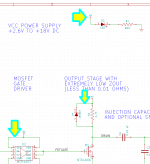
Honestly I don't remember. I recommend you use your multimeter on the "continuity" (beeper) setting, to figure out the answer on the PCB itself. Looking at the circuit schematic of the V4 Quasimodo, shown in post #1 of this thread and copied below, I observe that
so your beeper will quickly tell you which of the two LED thru-hole pads, is the anode.
And if you do happen to destroy the LED, don't fret! Amazon Canada will sell you a replacement for cheap:
link 1
link 2
link 3
Honestly I don't remember. I recommend you use your multimeter on the "continuity" (beeper) setting, to figure out the answer on the PCB itself. Looking at the circuit schematic of the V4 Quasimodo, shown in post #1 of this thread and copied below, I observe that
- LED anode (the "+" side of the LED) has continuity to D4 cathode
- LED anode has continuity to pin 1 of integrated circuit U2
- LED anode has continuity to pin 8 of integrated circuit U2
And if you do happen to destroy the LED, don't fret! Amazon Canada will sell you a replacement for cheap:
link 1
link 2
link 3
Attachments
Noob question here: for the green power led, does the long leg (anode) go to the square pad or the round pad?
The silkscreen pattern suggests that anode goes to square, but I want to be sure - I don't want to pay $15 shipping from Mouser for a single led!
cheers and many thanks, Derek
I see that you are in Toronto so I did a quick Google search and there are electronics stores in Toronto. One that I found:
SAYAL Electronics and Hobbies - Serving the Toronto area for 39 years!Sunday September 22, 2019 11:21:19 PM
SAYAL Electronics and Hobbies - Serving the Toronto area for 39 years!Sunday September 22, 2019 11:21:19 PM
I am in Vancouver and I go to a local electronics store, Lee's Electronics, for parts that I need in a hurry - no need to order from Mouser or Digikey for a single capacitor, resistor, etc, and no delay in completing a project.
When I order from Mouser or Digikey, I also order more than I need of the low priced parts that I may destroy or lose during construction so I have spares at hand.
Thanks Ben. All good. I've picked up basic supplies (incl. LEDs) from Sayal in the past. But these days I rely on the time-savings of online ordering.
And just in case someone has the same question about the LED orientation: yup, the long leg of the LED (anode, +ve) goes to the square pad.
And just in case someone has the same question about the LED orientation: yup, the long leg of the LED (anode, +ve) goes to the square pad.
success
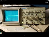
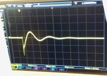
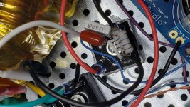
Thanks to Yoaudio for the board and the FET and Mark for the excellent circuit, I was able to find the perfect snubber for my Aleph J. The power transformer is a surplus toroid I bought years ago and weighs in at 7 Lbs. Based on the .15uf capacitor used , I came up with a series resistor value of 3.33 ohms. I have had the board for quite some time but my oscilloscope was broken. I have since replaced the old one with a ebay purchase.
Thanks to Yoaudio for the board and the FET and Mark for the excellent circuit, I was able to find the perfect snubber for my Aleph J. The power transformer is a surplus toroid I bought years ago and weighs in at 7 Lbs. Based on the .15uf capacitor used , I came up with a series resistor value of 3.33 ohms. I have had the board for quite some time but my oscilloscope was broken. I have since replaced the old one with a ebay purchase.
Attachments
Last edited:
Nicely done, @thompsontechs!
... although I'm afraid you can't join the Antique Tektronix Society with that digital oscillo-thingy....
... although I'm afraid you can't join the Antique Tektronix Society with that digital oscillo-thingy....
Nicely done, @thompsontechs!
... although I'm afraid you can't join the Antique Tektronix Society with that digital oscillo-thingy....
Funny you should mention the digital... I took me longer to figure out the scope than it did to build the circuit. 🙄 It's literally been 30 years since I did any work as a tech and the scope I used was the 5103.

QuasiGarmin
Thanks Mark, it was a fun little project and also got me learning the new scope, so it was beneficial in a couple areas. It also made my old synapses fire, which is always good for those of us over 50.
I got the V4 boards at MP audio Mike is a great guy, though customs coming into the US can be a bit of a hassle, the boards sat there for a week in limbo. Anyone seeking to do this job with the boards that Mark designed, can still get them from Mike MPAudio here https://www.mpaudio.net/product-page/quasimodo-no-math-transformer-snubber
Belated congratulations to both Elsheadphones, and thompsontechs! Success is a joyful thing.
Thanks Mark, it was a fun little project and also got me learning the new scope, so it was beneficial in a couple areas. It also made my old synapses fire, which is always good for those of us over 50.
I got the V4 boards at MP audio Mike is a great guy, though customs coming into the US can be a bit of a hassle, the boards sat there for a week in limbo. Anyone seeking to do this job with the boards that Mark designed, can still get them from Mike MPAudio here https://www.mpaudio.net/product-page/quasimodo-no-math-transformer-snubber
Last edited:
Belated congratulations to both Elsheadphones, and thompsontechs! Success is a joyful thing.
Congrats on the successful builds!!
Installed the subbers in my Aleph J. Waiting for it to warm up. It's a rany day outside, so it's a good day to do some serious listening
S
Cool, let us know what you think... I would like to have one switched to do a quick test, but I know the switch would also become part of the circuit and change the results, but it still might be fun try. Also, down the road, I might take some Quasi readings and make 2-3 combinations from flat to a bit off ring and see what those differences sound like, or if they are even audible to my old worn out ears.
- Home
- Amplifiers
- Power Supplies
- Simple, no-math transformer snubber using Quasimodo test-jig