Mark,
Thank you very much for your time and all the information.
I will check the remaining data out on this mosfet.
James
Thank you very much for your time and all the information.
I will check the remaining data out on this mosfet.
James
Mark,
Here you go. Please just let me know if I am right or wrong.
I appreciate the way you are not spoon feeding me information.
James
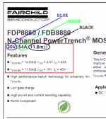
1. Yes, TO-220
2. Pinout is G D S
3. Maximum VDS is 30 volts
4. Maximum VGS is 20 volts
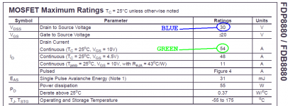
5. What is the maximum permitted value of IDS in amperes? 250uA
6. Does the first page of the datasheet mention the phrase "Logic Level Gate" ? preferred but not mandatory - no it does not.
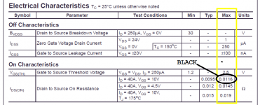
7. Is RDSon less than 0.010 ohms (< 10 milliohms is preferred)? Is RDSon less than 0.10 ohms? (< 100 milliohms is mandatory) - No, it is higher being 14.5 @ 4.5V and 11.6 @ 10V
Here you go. Please just let me know if I am right or wrong.
I appreciate the way you are not spoon feeding me information.
James
1. Yes, TO-220
2. Pinout is G D S
3. Maximum VDS is 30 volts
4. Maximum VGS is 20 volts
5. What is the maximum permitted value of IDS in amperes? 250uA
6. Does the first page of the datasheet mention the phrase "Logic Level Gate" ? preferred but not mandatory - no it does not.
7. Is RDSon less than 0.010 ohms (< 10 milliohms is preferred)? Is RDSon less than 0.10 ohms? (< 100 milliohms is mandatory) - No, it is higher being 14.5 @ 4.5V and 11.6 @ 10V
Mark,
Thank you very much for the reply and information.
I will reviewed your attached screenshots to see where I was wrong.
I also have the data sheet for the original MOSFET specified for this board that I will review as a comparison to further assist me in figuring out how I got that wrong.
Thank you very much again, James
Mark,
I apologize but maybe I am not understanding this, but with the question on Rds(on) being less than .010 ohms.
The MOSFET I ordered does not meet that criteria of being less than .010 ohms, but to me it does meet >100 millohms as I am reading the information.
I researched the formula for finding Rds(on) and it seems like it is a version (different names) of R=V/I. But even with this, I am not coming up with the same values as listed in the data sheet I posted.
Sorry but I am trying my best to understand this.
James
Your MOSFET will be perfectly adequate and a Quasimodo using it will work just fine.
Rds(on) is a MOSFET parameter which is measured, not calculated. It varies a little bit from one unit to the next, due to unavoidable variations in the manufacturing process. One example would be: gate oxide is slightly thicker on the left side of the semiconductor wafer than on the right. MOSFETs on the left side of the wafer will therefore have slightly higher Rds(on) than MOSFETs on the right side of the wafer. This is not desired, and the semiconductor fab engineers work their butts off to reduce its variation, but these sorts of small variations do occur.
So the manufacturer measures Rds(on) of every single MOSFET, and they throw away the ones whose measured value is higher than the datasheet spec.
Imagine how much money an unscrupulous dumpster-diver could make, by grabbing those reject units out of the garbage can and ... um ... finding a way to turn them into revenue.
Last edited:
Mark,
Thank you very much for the reply and information.
I am going through and reading the thread to try and understand as much of this as possible. I must say though, when you and the gentleman who wrote the article about diodes (I believe) are having a discussion it was making my head spin. It was a very interesting to read and I am still in that part of the thread but just the knowledge being placed in thread is very cool to read.
Thanks again, James
Thanks Mark for providing the PCB information. I can now have the PCB from China with a much lower cost, not to mention saving in shipping.
Is Rds(on) value critical on this circuit? I built the cheapomodo version and the 3 mosfets are 2N7008s (Rds(on)=7.5ohm each!)
Poting
Poting
You want Rds(on) as low as possible, so the MOSFET doesn't contribute any resistive damping to the secondary circuit. This is Best Practice and Good Hygiene in all cases, but pragmatically speaking it only makes a noticeable difference on a very few transformers, the ones with lowest self inductance. If you ever come across a situation where critical damping (zeta=1.0) occurs with a very VERY low value of Rsnub, say, below 10 ohms ... then I recommend you put Cheapomodo away and test again using a full fledged Quasimodo that has a MOSFET with Rds(on) below 20 milliohms.
Hi Mark,
Thanks for the clarification. The lowest Rs on my system is 15ohm, so it shouldn't be a serious problem. BTW, I'd recommend everyone consider adding a CRC snubber to their transformers. IMHO, the improvement is huge.
Poting
Thanks for the clarification. The lowest Rs on my system is 15ohm, so it shouldn't be a serious problem. BTW, I'd recommend everyone consider adding a CRC snubber to their transformers. IMHO, the improvement is huge.
Poting
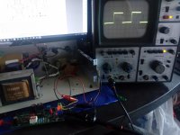
Hey Mark, see what wonderful square wave I measured from a 230VAC primary 12VAC 2A secondary transformer that's powering the filament heaters of an Unbalancer.
Attachments
Last edited:
One way to get a perfect square wave display when using Quasimodo, is to disconnect the transformer secondary from the Quasimodo PCB, and replace it with a 2.2 megohm resistor connected to Quasimodo. Voila, square wave.
An even easier way to get a perfect square wave display when using Quasimodo, is to disconnect ONLY ONE of the transformer secondary wires. Remove it from the screw down terminal block on the Quasimodo PCB and make sure it touches nothing else. {Notice what you just did: you introduced an OPEN CIRCUIT somewhere in the secondary.} Now power up Quasimodo and look at the waveform between TO SCOPE and ground. Voila, square wave.
An even easier way to get a perfect square wave display when using Quasimodo, is to disconnect ONLY ONE of the transformer secondary wires. Remove it from the screw down terminal block on the Quasimodo PCB and make sure it touches nothing else. {Notice what you just did: you introduced an OPEN CIRCUIT somewhere in the secondary.} Now power up Quasimodo and look at the waveform between TO SCOPE and ground. Voila, square wave.
@Mark
How to measure using two back to back transformers? I ask because I use two R-Cores primary 230V seconday two 21V 120VA each.
TIA
Felipe
How to measure using two back to back transformers? I ask because I use two R-Cores primary 230V seconday two 21V 120VA each.
TIA
Felipe
Here is my first time to test a transformer with my first ever ordered PCB-Quasimodo rig. I am excited!
I only have a very cheap Oscilloscope but it successfully displays the ringing waveform after playing with the settings.
Question:
Should I go for C or D? D seems a bit extreme and spiky.
The transformer Primary is set at 230V; secondary is 2x15Vac; 50VA.
Cs and Cx are the recommended values.
The final resistor value is about 27Ω. (for display C)
I hope I am doing everything correctly.
Thanks Mark for this wonderful tool!
Attachments
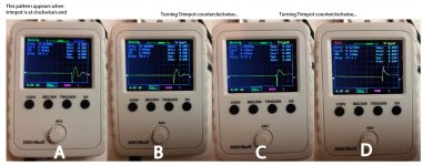
Nano, congratulations on a pretty build! This is the first one I've seen on a black PCB.
Among your photos, I would select "C". The second lumpity bumpity has just barely disappeared, exactly as we wish and exactly as the yellow arrowhead points, in the first few pictures of the Quasimodo .pdf
Among your photos, I would select "C". The second lumpity bumpity has just barely disappeared, exactly as we wish and exactly as the yellow arrowhead points, in the first few pictures of the Quasimodo .pdf
@Mark
How to measure using two back to back transformers? I ask because I use two R-Cores primary 230V seconday two 21V 120VA each.
TIA
Felipe
Is correct to measure like two separate transformers so two snubbers one for each transformer required?
- Home
- Amplifiers
- Power Supplies
- Simple, no-math transformer snubber using Quasimodo test-jig