I have 8 Quasimodo V4 through hole boards which I don't need.
Cost for 1 board is 2,20 Euro within EU / Switzerland, or 2,60 Euro Rest of World.
This is normal 100g letter postage - recorded delivery is also possible but La Poste charges 7,15 Euro for Europe or 8,15 Euro for Rest of World.
PM with your address if interested.
Cost for 1 board is 2,20 Euro within EU / Switzerland, or 2,60 Euro Rest of World.
This is normal 100g letter postage - recorded delivery is also possible but La Poste charges 7,15 Euro for Europe or 8,15 Euro for Rest of World.
PM with your address if interested.
Ouch! That Bill Of Materials says Mouser charges 3,47 Euros for a 1K trimmer potentiometer??
If you're unafraid to order from Asia, Futurlec sells them for USD 0.90 link 1
And Tayda sells them for USD 0.28 link 2
If you do order inexpensive trimmers from across the sea, I suggest you also think about ordering a 200 ohm trimmer and a 50 ohm trimmer at the same time. If and when you ever come across a transformer that requires a snubber resistor less than 200 ohms, you can pop in one of these extra trimmers and get fine-granularity adjustability.
I have 8 Quasimodo V4 through hole boards which I don't need.
Cost for 1 board is 2,20 Euro within EU / Switzerland, or 2,60 Euro Rest of World.
This is normal 100g letter postage - recorded delivery is also possible but La Poste charges 7,15 Euro for Europe or 8,15 Euro for Rest of World.
PM with your address if interested.
Boards posted today using international letter proirity postage.
tunasto - 1 board sent to Hungary
Sabrosa - 1 board sent to the US
PH104 - 2 boards sent to the US
The Peasant - 1 board sent to Canada
Johnny Canuck - 1 board sent to Canada
pgour - 1 board sent to Greece
2 boards left – awaiting payment from samoloko and ChesterBelle
All the boards are then gone.
For anyone who needs boards made. I had these made at https://www.seeedstudio.com/fusion_pcb.html , and from memory 10 boards cost about $18 incl shipping.
Last edited:
Complete Kit for Quasimodo V4 through hole
I still offer the complete kit since the post #468 with a number of happy posts here from customers ... The current price is $34.25 including the PayPal fee and free shipping to the lower states in the US. Add another $12.10 for international shipping.
The plastic bags with labeled parts and the PCB are shipped in a small carton box.
Please PM for a PayPal invoice.
Boards posted today using international letter proirity postage.
tunasto - 1 board sent to Hungary
Sabrosa - 1 board sent to the US
PH104 - 2 boards sent to the US
The Peasant - 1 board sent to Canada
Johnny Canuck - 1 board sent to Canada
pgour - 1 board sent to Greece
2 boards left – awaiting payment from samoloko and ChesterBelle
All the boards are then gone.
For anyone who needs boards made. I had these made at https://www.seeedstudio.com/fusion_pcb.html , and from memory 10 boards cost about $18 incl shipping.
Last two boards posted yesterday to Chesterbelle and pgour.
From Quasimodo post #1 at the top of the thread
... Answers to frequently asked questions:
- ...
- diyAudio members who have ordered their own sets of PCBoards from seeed and/or OSH Park, using the Gerbers provided here, include: gazzagazza, luvdunhill, Borges, stormsonic, cwtim01, normundss, dsolodov, EUVL, kissmurphy, stephengrenfell, Piersma. You can PM them to find out how easy or difficult it was.
Boards posted today using international letter proirity postage.
tunasto - 1 board sent to Hungary
Sabrosa - 1 board sent to the US
PH104 - 2 boards sent to the US
The Peasant - 1 board sent to Canada
Johnny Canuck - 1 board sent to Canada
pgour - 1 board sent to Greece
2 boards left – awaiting payment from samoloko and ChesterBelle
All the boards are then gone.
For anyone who needs boards made. I had these made at https://www.seeedstudio.com/fusion_pcb.html , and from memory 10 boards cost about $18 incl shipping.
Thank you very much.
It's really easy to order PCBs - and rewarding to share them around!
Thanks Mark for all the time and effort you have put in to making Quasimodo available and for all the support.
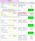
Last year in August I had an all to easy, event free experience with Seeed Studio making 10 of "V4 Through Hole" boards for a total, inc. postage to North Sydney Australia, of $AU32.10. I simply sent the provided Seeed files and got back the boards which look OK, see scan attached to my first post in this thread. I chose Seeed's cheapest option; the following cut and pasted from my Seeed completed orders page:
PCB Dimension - 5cm Max*10cm Max
Layer - 2
PCB Thickness - 1.6mm
PCB Qty. - 10
PCB Color - Green
Surface Finish - Hasl
Copper Weight - 1oz.
Panelized PCBs - 1
The boards are (99 x 46 x 1.6)mm and weight 14.6g each.
I made the surplus boards available to diyAudio members in Australia and New Zealand with the last three being posted out to three members this weekend.
I have no more available!
It was an easy, enjoyable and very rewarding experience, I received lots of thanks. I encourage others to do the same.
Cheers!
Rob
Thanks Mark for all the time and effort you have put in to making Quasimodo available and for all the support.
From Quasimodo post #1 at the top of the thread... Answers to frequently asked questions:
- ...
- diyAudio members who have ordered their own sets of PCBoards from seeed and/or OSH Park, using the Gerbers provided here, include: gazzagazza, luvdunhill, Borges, stormsonic, cwtim01, normundss, dsolodov, EUVL, kissmurphy, stephengrenfell, Piersma. You can PM them to find out how easy or difficult it was.
Last year in August I had an all to easy, event free experience with Seeed Studio making 10 of "V4 Through Hole" boards for a total, inc. postage to North Sydney Australia, of $AU32.10. I simply sent the provided Seeed files and got back the boards which look OK, see scan attached to my first post in this thread. I chose Seeed's cheapest option; the following cut and pasted from my Seeed completed orders page:
PCB Dimension - 5cm Max*10cm Max
Layer - 2
PCB Thickness - 1.6mm
PCB Qty. - 10
PCB Color - Green
Surface Finish - Hasl
Copper Weight - 1oz.
Panelized PCBs - 1
The boards are (99 x 46 x 1.6)mm and weight 14.6g each.
I made the surplus boards available to diyAudio members in Australia and New Zealand with the last three being posted out to three members this weekend.
I have no more available!
It was an easy, enjoyable and very rewarding experience, I received lots of thanks. I encourage others to do the same.
Cheers!
Rob
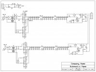
With transformer with two secondaries and two bridge rectifiers I do not see how reversing the phasing has any influence. I tried it in my system without any results. I wish to know theory behind it. On power supply schematic, any position is correct.C14 is in series with C8. So it is effectively across the power transformer.
Snubbing a schottky diode with a high value of capacitance is probably not a good idea. A capacitance of more then 500pF probably lets in more noise from the power line than it squelches.
Overall this is not a state of the art power supply design.
Better results would occur using a transformer snubber on each winding. Then using a full wave rectifier on each winding before filtering and regulation. The common or ground can best be combined after all of this. Another added technique is to reverse the phasing on the two transformer windings feeding the pair of bridge rectifiers and then adding a rail to rail capacitor to the outputs.
With transformer with two secondaries and two bridge rectifiers I do not see how reversing the phasing has any influence. I tried it in my system without any results. I wish to know theory behind it. On power supply schematic, any position is correct.
It is a technique to cancel HF noise riding in on the power line. The simplest version is to put a capacitor from the dot on one winding to the not dot on the other and a second capacitor from the dot on the second winding to the not dot on the first. This makes an easy to measure drop in power line noise. (If you have the right equipment.).
As to the effect it had on what you perceive that depends on your transformer winding balance, equipment, location etc.
But you do get a star for trying it.
My transformers are flatpack PCB type with split primary and sec.It is a technique to cancel HF noise riding in on the power line. The simplest version is to put a capacitor from the dot on one winding to the not dot on the other and a second capacitor from the dot on the second winding to the not dot on the first. This makes an easy to measure drop in power line noise. (If you have the right equipment.).
As to the effect it had on what you perceive that depends on your transformer winding balance, equipment, location etc.
But you do get a star for trying it.
There are no capacitors connections you have described, in your PS which is attached.
Attachments
My transformers are flatpack PCB type with split primary and sec.
There are no capacitors connections you have described, in your PS which is attached.
That is an older and more complicated design. Measured it had 20 dB less noise pass than the two winding version. The simpler version just uses a single transformer and the capacitors to cancel the line noise. Still a work in progress. Just added some test equipment to do a bit more investigation of noise paths.
As to the flat pack design I have some that are great and some that mis-match by 5% or so. A quick check of the AC voltage on each secondary will show the match quality.
Unfortunately I buy used gear off eBay I do have to go some repair to the new gear before use.
Q2 is a shunt regulator feeding a series pass follower. A common circuit before IC regulators became available.
In fact the circuit in #1112 was the grandfather of Walt Jung's "Pooge 5.51" super duper voltage regulator; Walt replaced R1 by a PNP constant current source, and added a PNP emitter follower between the collector of Q2 and the base of Q1. He also added a couple flourishes and pirouettes that I encourage "serious students of the art" to look up: R859 and Rr3. Google for walt jung pooge 5.51Q2 is a shunt regulator feeding a series pass follower. A common circuit before IC regulators became available.
Are they any PCBs left in someone's drawer? I would buy one...
I would like to buy one to.
- Home
- Amplifiers
- Power Supplies
- Simple, no-math transformer snubber using Quasimodo test-jig