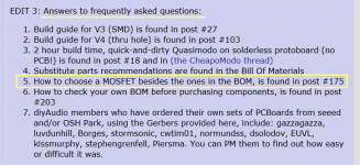
So, when I first assembled my board I had M1 in backwards and I let the smoke out of U2. Funny thing is, after turning M1 around I can still get wave forms out of it, but putting anything more than 5V in U2 gets very hot. So I guess I'm replacing U2, but what else did I damage?
![IMG_1828[1].jpg](https://www.diyaudio.com/community/data/attachments/561/561257-bcbe14c4f191f26472971f65a127e9f4.jpg?hash=vL4UxPGR8m "IMG_1828[1].jpg")
Hi folks,
Forgive my ignorance but I joined the Quasimodo fun a tad late.
Would you be so kind as to tell me where to get the PCB boards and the parts necessary to construct a V4 ?
Many thanks.
Q.
p.s. I live in Canada
Forgive my ignorance but I joined the Quasimodo fun a tad late.
Would you be so kind as to tell me where to get the PCB boards and the parts necessary to construct a V4 ?
Many thanks.
Q.
p.s. I live in Canada
I have just successfully finished and tested my Quasimodo. Thank you to Mark Johnson for designing this fantastic tool and thank you to stephengrenfell for the pcb!
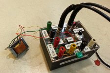
I built mine as a super deluxe version with a nice case and binding posts for connections. A 1K ten-turn potentiometer with a vernier dial was used so that I can get an approximate resistance reading directly off of the dial. There are binding posts for connecting an external resistor which can also be used for measuring the internal potentiometer when it is selected. BNC connectors were installed for the oscilloscope signal and sync connections. Power supply is from a wall-wart feeding a 7815 regulator.
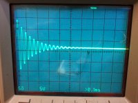
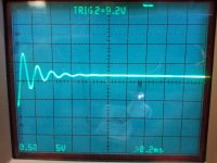
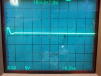
Below are some pictures of the unit in action, including scope shots of a small transformer under test with the potentiometer switched out of the circuit, at the maximum setting of 1K ohms, and at close to the optimum setting. I can't wait to start testing and adding snubbers to my audio gear!
Take care,
Doug
I built mine as a super deluxe version with a nice case and binding posts for connections. A 1K ten-turn potentiometer with a vernier dial was used so that I can get an approximate resistance reading directly off of the dial. There are binding posts for connecting an external resistor which can also be used for measuring the internal potentiometer when it is selected. BNC connectors were installed for the oscilloscope signal and sync connections. Power supply is from a wall-wart feeding a 7815 regulator.
Below are some pictures of the unit in action, including scope shots of a small transformer under test with the potentiometer switched out of the circuit, at the maximum setting of 1K ohms, and at close to the optimum setting. I can't wait to start testing and adding snubbers to my audio gear!
Take care,
Doug
Attachments

Nice build! So you can watch resistance in real time as you adjust for zeta=1?
Thank you! Yes, you get an instant display of the resistance at all times just by looking at the vernier. It's accurate to within about 20 ohms.
Take care,
Doug
Oh, I thought you had your meter connected as you made adjustments.
No, connecting an ohmmeter to the circuit while it is in operation would inject a DC current that would mess things up I'm sure. However, if you did want to connect a meter to measure the resistance real-time, then using a dual-gang potentiometer could work for that. One gang would be connected to the Quasimodo as usual and the other gang connected to some binding posts for the ohmmeter to connect to. This would probably be a bit more accurate than the vernier method depending on the tracking accuracy between the two potentiometer gangs. High quality dual-gang ten-turn potentiometers are pretty expensive though.
Take care,
Doug
I have just successfully finished and tested my Quasimodo. Thank you to Mark Johnson for designing this fantastic tool and thank you to stephengrenfell for the pcb!
I built mine as a super deluxe version with a nice case and binding posts for connections. A 1K ten-turn potentiometer with a vernier dial was used so that I can get an approximate resistance reading directly off of the dial. There are binding posts for connecting an external resistor which can also be used for measuring the internal potentiometer when it is selected. BNC connectors were installed for the oscilloscope signal and sync connections. Power supply is from a wall-wart feeding a 7815 regulator.
Below are some pictures of the unit in action, including scope shots of a small transformer under test with the potentiometer switched out of the circuit, at the maximum setting of 1K ohms, and at close to the optimum setting. I can't wait to start testing and adding snubbers to my audio gear!
Take care,
Doug
Very nice build Doug! Great idea for the vernier dial on the pot. I'll have to check my stock of 10 turn pots to see if I have any low value ones. I've ordered a couple of boards on the group buy.
Brian
Very nice looking, congratulations! By the way, capacitor "Cs" is in series with the potentiometer and prevents DC current from flowing. So if you measure Rs in-circuit, without bothering to removing it from Quasimodo, your ohmmeter will give the correct answer. However, you probably want to turn off Quasimodo's square wave oscillator (cut the power supply) when reading the ohmmeter, lest the wiggly bumpy waveform corrupt the ohms measurement.
Another member's V4 build using a 10 turn vernier potentiometer, is pictured in post #952.
Another member's V4 build using a 10 turn vernier potentiometer, is pictured in post #952.
That turns-counting pot is a terrific idea - I missed that first time thru this thread. I'm about ready to start my builds of Mark's Quasimodo and PhaseDot boards. I might try a rotary switch to switch out say half-dozen different caps in the Quasimodo.
Hello,
I'm building my V4.
What I can use in place of the NTD4906 that I'm not able to find?
Regards
Guglielmo
I'm building my V4.
What I can use in place of the NTD4906 that I'm not able to find?
Regards
Guglielmo
I did a quick check on parts available at Digikey and the following look like they would work well - NTD4815 or NTD4858.Hello,
I'm building my V4.
What I can use in place of the NTD4906 that I'm not able to find?
Regards
Guglielmo
Good luck.
---Gary
Welcome, new readers from the Quasimodo V3 and V4 PCB Group Buy! You supported a good cause; thank you for your generosity.
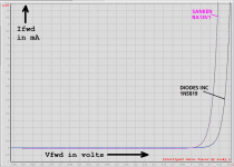
For those who can't leave well enough alone, and who fervently desire to soup up their V4 Quasimodo to hot-rod status, I offer this idea: install lower Vfwd diodes in positions D1 and D3. Instead of 1N5819, use the Sanken RA13V1 Schottky diode. This morning I put them both on a curve tracer and found that the datasheets were right: the RA13 does have significantly lower Vfwd.
Unfortunately, Sanken doesn't seem to offer this device in the SOT-23-3 package.
Enjoy!
_
Attachments

- Home
- Amplifiers
- Power Supplies
- Simple, no-math transformer snubber using Quasimodo test-jig