Dear Mr. Johnson,
Now that you have settled how to settle the spikes between the transformer secondaries and the rectifiers I wonder what you think of what happens at the primary?
I see caps used across the AC and wonder if there is a best value for this?
Can QUASIMODO be used in reverse?
Or is this a simple one size fits all application?
Quasimodo solves the problem of transformer secondary ringing, due to fast dI/dt from rectifier turnoff.
It seems to me that if you hope to use it to solve some other problem related to the AC mains (transformer primary), you first need to define what that problem actually is. I have no idea what it might be.
I've seen power supply designs for audio equipment, which include surge suppression on the primary side of the transformer. I've also seen RFI filters, common-mode chokes, inrush current limiters, and ON/OFF switch contact arc quenching in audio equipment. But I don't think Quasimodo is the right tool to optimize any of those.
Hi,
I have a dual secondary transformer which is connected with the bridge rectifier and smoothing caps.
Since I can't break the connection between transformers secondary and the rectifier brigde how can I properly test for the zobel?
I have to short only the primary or primary and the 2nd secondary too?
I have never tried to attach Quasimodo to anything but a disconnected and floating transformer secondary, so I don't know what will happen.
If you connect a bridge rectifier and filter capacitors to the secondary, I suspect it may ruin the bell-ringing action. But why not try it anyway, the worst that can happen is, you overheat and possibly melt the MOSFET on the Quasimodo PCB. Which you can replace for less than $3.00 in less than 30 minutes.
If you connect a bridge rectifier and filter capacitors to the secondary, I suspect it may ruin the bell-ringing action. But why not try it anyway, the worst that can happen is, you overheat and possibly melt the MOSFET on the Quasimodo PCB. Which you can replace for less than $3.00 in less than 30 minutes.
The cheapomodo worked without problems with attached rectifier and CRCRC filter (10kuF-0R46).
At least no problems that I noticed after trying to adjust it taking pictures for more than an hour.
At least no problems that I noticed after trying to adjust it taking pictures for more than an hour.
Last edited:
Fortunately the mosfe didn't melt.
If I tune the zobel with only the primary shorted and after short the 2nd secondary too I will get a strange bump instead a concave line.
This turns shortly concave if I lower the resistor value for the zobel and very shortly under damped if I still go low with the pot. It seems like the pot has a faster action.
I will use the resistor value that quasimodo calculated without the 2nd secondary shorted.
Thank you.
Since I have another similar ps(is different only the transformer🙂 ) and another transformer as the one on the ps but not connected I did another test.
For the transformer that is floating quasimodo gave 9r, for the one on the ps gave 24r and 11r with 2nd secondary shorted.
So guess I was wrong to think I can use the value quasimodo calculated without doing the short on the 2nd secondary.
For the transformer that is floating quasimodo gave 9r, for the one on the ps gave 24r and 11r with 2nd secondary shorted.
So guess I was wrong to think I can use the value quasimodo calculated without doing the short on the 2nd secondary.
Since I have another similar ps(is different only the transformer🙂 ) and another transformer as the one on the ps but not connected I did another test.
For the transformer that is floating quasimodo gave 9r, for the one on the ps gave 24r and 11r with 2nd secondary shorted.
So guess I was wrong to think I can use the value quasimodo calculated without doing the short on the 2nd secondary.[/]
Your results do not definitively answer the question, while adding some confusion. If I am reading your post correctly you say you tested one transformer for one condition and then a second transformer for the second condition without any proof they will measure identically in the situation and would be the equivalent of testing one for both conditions. At this point the resulting variations in resistances you describe could be attributed to slight transformer differences. Test and compare the same transformer for both of the conditions, repeat since you have two for twice the data points, or show why the two samples you tested can be relied upon to measure identically to just one.
He did.
For the in circuit test he got 9r.
For the isolated transformer he got 11r to compare with the 9R for "in circuit".
And he got 24r for the no connection to the other secondary.
That to me looks like he is confirming that the shorted secondary gives close agreement and that the "in circuit" test gave close agreement.
The only result that is many ohms away is the open second secondary, which is not the recommended way to test.
He got measurements sure, and they support an answer. Without major assumption, why are the differences in the measured results he got between two transformers taken in different conditions not just as attributable to transformer variations? The only information provide about them is that they are similar? Seems vague enough to question so I have.
Hi to all.
I have an amp psu with a center tapped transformer.
I followed the connection direction as described at the datasheet, p.11 fig.13 "Center Tapped Secondary"
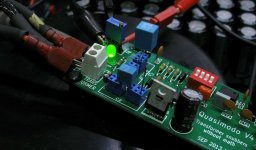
The initial measuring was the following
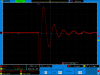
As decreased the variable resistor values the capturing was:

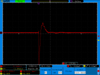
With the last final position to:
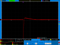
As you can see, there is no any smooth snubbering, but why? Any suggestion is welcome!
I have an amp psu with a center tapped transformer.
I followed the connection direction as described at the datasheet, p.11 fig.13 "Center Tapped Secondary"

The initial measuring was the following

As decreased the variable resistor values the capturing was:


With the last final position to:

As you can see, there is no any smooth snubbering, but why? Any suggestion is welcome!
The previous captures was with Cx=0.01uF, Cs=0.15uF, R=28R.
I saw at the psu of my amp that it uses Wima 0.1uF/63V parallel with each diode. As described at the datasheet p.6 fig.8 these capacitors are the same position of Cx.
I tried this Cx 0.1uF value with the Cs=1uF and the final capture was OK with 11R resistor.
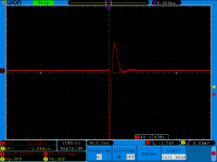
I saw at the psu of my amp that it uses Wima 0.1uF/63V parallel with each diode. As described at the datasheet p.6 fig.8 these capacitors are the same position of Cx.
I tried this Cx 0.1uF value with the Cs=1uF and the final capture was OK with 11R resistor.

did you remove the capacitors in parallel to each rectifier diode?
Cx is across the transformer secondary, i.e. across the ~ to ~ of a bridge rectifier, not across the diode.
Cx is across the transformer secondary, i.e. across the ~ to ~ of a bridge rectifier, not across the diode.
Andrew thanks for the reply.
No, I didn't removed them. My test wasn't on the psu circuit.
This psu is from Aaron No3 Millennium. The 500-600VA transformer has +35.9/0V/–35.9 Vac secondary.
First, I removed the secondary from the psu and make the appropriate shorting at the primaries. I used the suggested Cx and Cs values on Quasimodo Test, as described at the datasheet but I haven't smooth capture.
Then I read again the datasheet and I saw at p.5-6 fig.8 Mark's notes for the Self’s Elektor Preamp-2012, that the C15...C17 with the 47nF (parallel to each diode) is the Cx (p.5 at the end), this psu is center tapped also.
At the last, I used the 0.1uF as Cx and 1-1.5uF to Cs and the results was OK, as you see.
I see, that the Cx is across the transformer secondary, but I have confused with the Mark's prompt for the Elektor Preamp.
Sorry for my English...
I still don't follow.
Have you used two Cx and two Cs, one of each across each secondary of the centre tapped?
Have you used two Cx and two Cs, one of each across each secondary of the centre tapped?
At the Quasimodo test, no.
I shorted one of the secondary windings to the center tap, and connect the other winding and the center tap to Quasimodo. I used one Cx and one Cs on quasimodo test pcb. As the 1st photo on my 1072 post.
It wasn't OK?
I shorted one of the secondary windings to the center tap, and connect the other winding and the center tap to Quasimodo. I used one Cx and one Cs on quasimodo test pcb. As the 1st photo on my 1072 post.
It wasn't OK?
Yes, now I follow that.
Replicate that on one side of the centre tapped secondary
and replicate again on the other side of the centre tapped secondary.
Back to the pics:
what is the difference between last pic in post1072 and the pic in post1073?
Replicate that on one side of the centre tapped secondary
and replicate again on the other side of the centre tapped secondary.
Back to the pics:
what is the difference between last pic in post1072 and the pic in post1073?
How to put the right values on centered tapped secondary, I think that Mark's notes are described very well and they are identical as your proposal.
I don't have problem with that.
My problem is the right procedure quasimodo test. At the post 1072 results, I used as I told the Cx=0.01 and Cs=0.1-0.15uF but with no smooth capture.
Because I didn't know why this happening, then I tried (post 1073) other values on Cx and Cs on quasimodo test. I saw that if I used Cx=0.1uF and Cs=1uF with 11R the result is fine OK.
I am wondering about the parallel capacitors on diodes! Can I leave them as Cx or not? And why the Mark suggests this on Preamp's example (p.5-6 fig.8)?
- Home
- Amplifiers
- Power Supplies
- Simple, no-math transformer snubber using Quasimodo test-jig