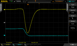
This one comes from a 5 VDC regulated wall wart. Note the time offset, -1.694z. WTH is a zsecond?
A Z second is 10 to the minus Z seconds.😀😀😀
🙄🙄🙄
A Z second is 10 to the minus Z seconds.
I looked it up after that and it's a zeptosecond. A zeptosecond is a trillionth of a billionth of a second (10^-21 seconds). I knew the Rigol scope was a decent value, but I didn't realize how good!
Well, I'm not sure if a "0" point in time not equal to zero is a real strength... 😕
Looks more like buggy software to me, i.e. not rounding/calculating correctly. 😎
😉
Winfried
Looks more like buggy software to me, i.e. not rounding/calculating correctly. 😎
😉
Winfried
It is completely your decision. The easiest thing to do is put the snubber in and listen to the gear for six or twelve months. Then take out the snubber and listen to the gear some more. Did the sound get worse, get better, or stay the same? Now you know with absolute certainty, which arrangement you prefer.
Yes I know is my decision. I compared with vs without snubber. What I ask you is your opinion about technical reasons to use or not to use.
TIA
This is a perfect opportunity to try the active bridge and see what the results are from snubbing - the waveform of the transistor turn-off is unquestionably going to be different from any diode, so it’s unknown territory, and any measurements you find and post will be very appreciated!
I look forward to seeing what you learn.
I look forward to seeing what you learn.

Congratulations, aterren! Your board seems to be working well.
Those numbers on bottom left (34.5mV ; 200mV) are a little concerning; maybe you might have set the vertical amplifier soft-knobs to expect a 1X probe when you're actually using a 10X probe, or something along those lines.
Those numbers on bottom left (34.5mV ; 200mV) are a little concerning; maybe you might have set the vertical amplifier soft-knobs to expect a 1X probe when you're actually using a 10X probe, or something along those lines.
Mr. Johncons,
Thank you for the attention to detail. You are correct, the probes are 10x and the scope was set for 1x. Thankfully, in this case the absolute number was not important.
A general question if I may:
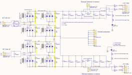
In the attached schematic (from an old DIYAudio group buy) is there any benefit to having a snubber across each diode as shown versus using a CRC snubber in place of C1?
Thank you for the attention to detail. You are correct, the probes are 10x and the scope was set for 1x. Thankfully, in this case the absolute number was not important.
A general question if I may:
In the attached schematic (from an old DIYAudio group buy) is there any benefit to having a snubber across each diode as shown versus using a CRC snubber in place of C1?
Attachments
Uhh .. that's pretty high, unless its a high voltage supply.
How does the waveform look? The magic of this method is, 'If the waveform looks right, you're done!'😉
Sorry if I'm clumsily stepping on toes, MJ😱
Cheers
How does the waveform look? The magic of this method is, 'If the waveform looks right, you're done!'😉
Sorry if I'm clumsily stepping on toes, MJ😱
Cheers
... is there any benefit to having a snubber across each diode ... versus using a CRC snubber in place of C1?
No. That approach arises from an incorrect assumption: "if the diodes cause the transformer secondary circuit to ring, then maybe we can fix the problem by twiddling around with the diodes?" which is wrong. You fix the problem by adding a damping resistor to ruin the "Q" (increase the "zeta") of the resonant circuit.
Uhh .. that's pretty high, unless its a high voltage supply.
How does the waveform look? The magic of this method is, 'If the waveform looks right, you're done!'😉
Sorry if I'm clumsily stepping on toes, MJ😱
Cheers
The waveform looks good with 9K1, if not OK usign this high value & to use lower Rs value it's possible to change the value of caps? wich values?
No. That approach arises from an incorrect assumption: "if the diodes cause the transformer secondary circuit to ring, then maybe we can fix the problem by twiddling around with the diodes?" which is wrong. You fix the problem by adding a damping resistor to ruin the "Q" (increase the "zeta") of the resonant circuit.
Thank you.
O.K., merlin, but is it high voltage and/or a valve-rectifier? 9100 ohms might be almost reasonable, if the voltage is high enough.
Still wondering -- but if 'the waveform looks good', that probably cinches it.😉
Regards
Still wondering -- but if 'the waveform looks good', that probably cinches it.😉
Regards
Last edited:
Mosfet replacement - Infineon?
I just picked up a Quasimodo v4 pcb that someone could spare. However, I just noticed that the OnSemi MOSFET is hard to come by. I was digging around in the Mouser catalog and was curious to see if this one would fit the bill. It seems to come close to the characteristics that Mark pointed out, it's through-hole, and has the same pin out. Thoughts?
Infineon MosFET
- Home
- Amplifiers
- Power Supplies
- Simple, no-math transformer snubber using Quasimodo test-jig