Anyone got a Quasimodo pcb for sale?
Considering ordering from JLC-PCB
Where are you located? I have a v4 PCB (through hole) I will send you for free if located in US.
PM me if interested. Giving something back for what this site has given me.
Regards,
Don
Where are you located? I have a v4 PCB (through hole) I will send you for free if located in US.
PM me if interested. Giving something back for what this site has given me.
Regards,
Don
Thanks Don, PM sent.
I hope/plan to build one of these in the future, however, I have a time-sensitive project for which I need to figure out a snubber value. Is there anyone in New Jersey who'd be willing to loan me theirs?
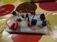
A lot of people have successfully optimized a C+RC snubber using a bellringer test jig NOT built on a printed circuit board. Which makes sense to me, since I developed and prototyped the idea on a solderless breadboard using pluggy wires. It worked quite well.
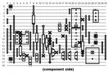
The reduced-complexity, little brother called "Cheapomodo" (here is a link) goes together even faster. Have a look at the attached images to see examples of the creativity of other diyAudio members!
_
The reduced-complexity, little brother called "Cheapomodo" (here is a link) goes together even faster. Have a look at the attached images to see examples of the creativity of other diyAudio members!
_
Attachments
-
 cheapo_1.jpg790.7 KB · Views: 465
 -
 cheapo_10.jpg292.9 KB · Views: 192
 -
 cheapo_9.JPG300.1 KB · Views: 180
 -
 cheapo_8.png92.4 KB · Views: 188
 -
 cheapo_7.png110.5 KB · Views: 200
 -
 cheapo_6.JPG287.4 KB · Views: 186
 -
 cheapo_5.jpg693.9 KB · Views: 372
 -
 cheapo_4.jpg87.1 KB · Views: 463
 -
 cheapo_3.jpg302.6 KB · Views: 459
 -
 cheapo_2.jpg619.6 KB · Views: 456
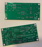
Hey everyone, I wanted to build a Quasimodo and needed PCB for myself. So, I had batch made and have extras. If you'd like one, shoot me a PM. The boards are thru-hole V4. I'd prefer to send these only within the US. The cost is $5, including shipping. I will send them in a letter envelope via US Mail.
I also ordered extra parts from Digi-Key for the build, so I have a few parts kits available. I need to figure out the cost on those and the best way to ship them, as those probably won't work in a letter envelope. They will be priced at cost.
I also ordered extra parts from Digi-Key for the build, so I have a few parts kits available. I need to figure out the cost on those and the best way to ship them, as those probably won't work in a letter envelope. They will be priced at cost.
Attachments
j_thomas, congratulations! It's always great news when someone successfully orders PCBs without difficulty. Thanks from everyone for your generous offer of boards and kits, too.
Mark
Mark
Mark what about to use Quasimodo for active rectifiers like used by Prasi & Tibi?
Tibi said isn't necessari due to mosfet capacitance.
Tibi said isn't necessari due to mosfet capacitance.
A lot of people have successfully optimized a C+RC snubber using a bellringer test jig NOT built on a printed circuit board. Which makes sense to me, since I developed and prototyped the idea on a solderless breadboard using pluggy wires. It worked quite well.
The reduced-complexity, little brother called "Cheapomodo" (here is a link) goes together even faster. Have a look at the attached images to see examples of the creativity of other diyAudio members!
_
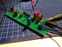
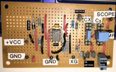
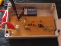
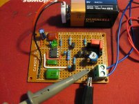
Mark, this is such a cool gizmo! I put together a full Quasimodo with twisty wires on a piece of single-sided full copper Vectorboard. I had a lot of the parts in my bins except for the Mosfet, driver, and the diodes. In the attached pix you can see the NTE caps(!) and the forty year old ICM7555IPA(!!). It's powered by a 9 VDC regulated wall wart that I modified with some ideas from Rod Elliott and snubbers for the transformer using the Quasimodo jig.
I have used the Quasimodo jig in the rebuild of a power supply for a failed PS in an electronic crossover (ceramic caps across the rectifier diodes—without resistors—carbonized and took out the toroidal transformer) and on some wall wart supplies on a few other small audio devices. I did some tests on a bunch of other transformers that I'll post pix of downthread.
Many thanks for a fun little device!
Attachments
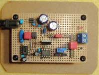
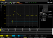
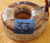
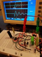
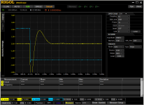
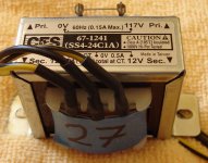
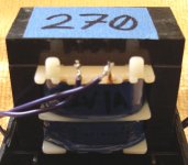
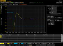
This next one is a part I picked up from a local supplier for an older project. They were cheap so I bought two. Regular old E-I type transformer. You can see in the trace after 1.5usec there's just a hint of lumpty bump. Thirty-three ohms is close enough to not have to go nuts finding a 31.575 ohm resistor.
Attachments
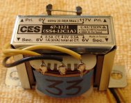


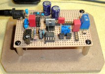
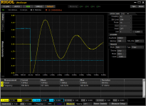
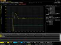
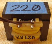
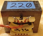
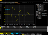
This one got harvested out of a no-name wall wart and is one of those over/under winding E-I transformers that seem to be so popular with overseas manufacturers. Note the high frequency of the ringing on the lumpty bump trace and the pointy shape of the trace on the snubbed trace. Two hundred twenty ohms was close enough to flat.
Attachments

There's no need to AC couple either the blue trace or the yellow trace, they're both fairly well behaved. In fact if you DC couple the blue trace you can set its trigger level at (supply_voltage / 2) even before hooking up the probes to the circuit board.
Also I think they ought to discipline the bozo at Rigol, who thought it was a good idea to display 211 yoctoseconds across the horizontal axis.
Also I think they ought to discipline the bozo at Rigol, who thought it was a good idea to display 211 yoctoseconds across the horizontal axis.

Mark what about to use Quasimodo for active rectifiers like used by Prasi & Tibi?
Tibi said isn't necessari due to mosfet capacitance.
?

There's no need to AC couple either the blue trace or the yellow trace, they're both fairly well behaved. In fact if you DC couple the blue trace you can set its trigger level at (supply_voltage / 2) even before hooking up the probes to the circuit board.
Also I think they ought to discipline the bozo at Rigol, who thought it was a good idea to display 211 yoctoseconds across the horizontal axis.
I shall take this under advisement as I'm recapping an amplifier now—just waiting for some parts. All-in-all, this is a really nice little device. I'm really impressed at how well it works in all the iterations we have come up with.
Thanks again!
Mark what about to use Quasimodo for active rectifiers like used by Prasi & Tibi?
Tibi said isn't necessari due to mosfet capacitance.
I will appreciate your opinion. Also I have 150VAC 0.2A tx needed 9k1 I guess too much high, theres is a way to calculate other capacitors values?
It is completely your decision. The easiest thing to do is put the snubber in and listen to the gear for six or twelve months. Then take out the snubber and listen to the gear some more. Did the sound get worse, get better, or stay the same? Now you know with absolute certainty, which arrangement you prefer.
- Home
- Amplifiers
- Power Supplies
- Simple, no-math transformer snubber using Quasimodo test-jig