Hi darkfreniz,
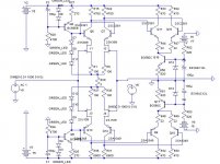
I wanted the option for global feedback - in which case you used R52 and R49 or if you wanted to keep the output stage outside the feedback loop - use R52, R50 and R51.
C13 was added for compensation but was not needed in practice.
Regards,
Jam
PS. I suppose you could use all four resistors if you wanted to use nested feedback loops.
amplifierguru said:Conventional power amplifiers commonly feature a low voltage gain input differential stage followed by a very high voltage gain stage then usually a unity gain emitter or source follower. This design suffers from a distinct topological deficiency that degrades the sound and is responsible for inferior sound quality.
The typical gain distribution is shown in the thumbnail where the weakness of PSRR of the input stage ( not amplifier) due to the divider with stage output Z vs load Z determines intrusion of Class AB PS artefacts which are magnificently amplified by the very high gain Vas to output, blurring the stereo image detail and spatial info and raising the dependance for performance on the PS quality!
Better sound quality from such a design centres around fiddling at the edges of this flawed topology rather than adopting a new one.
amplifierguru,
So, we want much gain in the stage with the error correction, mostly differential. But with Jfet's it's hard to have many gain, and with BJT's you will bias the VAS stage to havily, with many gain in the first stage.
One question, can I assume that a dual differential (output off the first connected to the gates off the second diff pair) is one stage?? This way I can have relative high gain (X200) and have no problem biasing the next stage to high.
To me it looks that way. Also, can anybody tell me what a normal gain (not gain actually but amplifying factor) is in an amp? I've seen design's with X1000 and X20000.
See attachment.
Cheers
Ben
Attachments
Hi Benson,
Yes you can certainly achieve similar gains over two non-bootstrapped stages but look at the added complexity. Also you need to tailor the responses of these two stages into ideally a single pole response - if to meld with something like my complementary EF driver and SF output - which has a response pole at 100KHz.
Regarding gain you could easily set your first two stages at 5000 or 25000 depending on your need for low or high NFB. The output stage is only average 40 but declines from 100KHz.
Cheers,
Greg
amplifierguru said:.........real improvement can be obtained by reducing the gain of the Vas e.g. with R to ground.
No...
amplifierguru said:
Then there's the overbuilding (wasteful) necessary to compensate for the POOR PSRR - double x'former VA and double PS C - all for 6dB audible improvement.
Complete red herring i fear....one merely has to use a simple RC filter to drop ripple below noise...

Hi Mikeks,
You're one of Omar's spawn, right? Sniping again?
RC filtering just doesn't work at power demand supply bounce frequencies - but you know that!
Have you come to terms with the A1A2A3 scenerio yet, no mention of that?
Cheers,
greg
You're one of Omar's spawn, right? Sniping again?
RC filtering just doesn't work at power demand supply bounce frequencies - but you know that!
Have you come to terms with the A1A2A3 scenerio yet, no mention of that?
Cheers,
greg
Contest: What do we have to say or claim in order to get a YES from Mike? 
Mike, there are many NO's from you, without any explanation.
Mike, there are many NO's from you, without any explanation.
Mikeks meaning RC filtering of supply voltage feeding A1A2... yes? 
Greg,
what IRFP are you using, I guess IRFP240/9240, or actually the N versions as the other are obsolete I guess.
Cheers Michael
Greg,
what IRFP are you using, I guess IRFP240/9240, or actually the N versions as the other are obsolete I guess.
Cheers Michael
Greg,
Are your kits ready for sale and if so a photo of what comes in the kit would be great.
Thanks.
Regards,
Jam
Are your kits ready for sale and if so a photo of what comes in the kit would be great.
Thanks.
Regards,
Jam
Ultima Thule said:Mikeks meaning RC filtering of supply voltage feeding A1A2... yes?
Yes...Thanks Ultima...(at last i get to say a 'yes!' 🙂 )
...covered to perfection by D. Self of course...no mystery there....
Yes Ultima Thule IRFP240/9240 (or 9140<50V supplies) . What's obselete?
Hi Jam just waiting for some parts - maybe a week.
Well hi Mikeks,
lets see a schematic then of a SIMPLE diff'l (A1) and Vas (A2) with 40dB of 20Hz filtering of the supplies that hasn't lost output swing and doesn't thump at turn on requiring a relay? Mine doesn't.
Are you up to it??
Cheers,
Greg
Hi Jam just waiting for some parts - maybe a week.
Well hi Mikeks,
lets see a schematic then of a SIMPLE diff'l (A1) and Vas (A2) with 40dB of 20Hz filtering of the supplies that hasn't lost output swing and doesn't thump at turn on requiring a relay? Mine doesn't.
Are you up to it??
Cheers,
Greg
amplifierguru said:Yes Ultima Thule IRFP240/9240 (or 9140<50V supplies) . What's obselete?
Cheers,
Greg
Hi Greg,
ok, 9140 should be more complementary to 240's...
Obsolete - sorry for the inconveniences, I have mixed up some things here...

In general:
Don't know, the "problem" to see the PS commutation arteffects in an amplifier circuit of general type is maybe because people forget that the signal refference amplified is actually swaping from earth to rail voltages after A1, and from here to the "other side" of A2 the signal refference is again swapped back to earth without thinking that A2 will be balancing between two refferences that are not at all constant, and with H2 and H3 of 20 kHz means... yeah that goes strait through the miller capacitor.
With a VAS stage with huge gain and output impedance the tiny miller capacitance will still have a noticeable effect on A2 stage performance with respect to PS commutation, but the problem can be solved of course, eg. the general VAS type can be improved, right?!
Normaly clever use of clamping technics with simple solutions can very well take care of thumping I believe, perhaps zener diodes in parallel with R in the RC filter, well it's non-issiual things.. just annoying the "KISS guy" if the omni-amp-design-smartness is not inherent in the circuit without adding more components, ultimately it should be just one amplifying component, eg. a wire with gain? 😉
But if we would design with a general VAS stage, what would you do to cope with PS commutation arteffects?
I mean I would add a ridiculously small ~10VA (2x12V or so) transformer ontop of the heavy PSU feeding A3, and actually use high performance regulation feeding A1A2, yes it adds up to complexity, but I'm not afraid of it, not any beefy things really... 🙂
Your thoughts?
Cheers Michael 🙂
Hi Michael,
You had me worried there for a moment as I've just characterised the differential tempco's of IRFP240/9240 at 50mA!
You have to appreciate where I'm leading with this - an amp that is not only simple, low parts count and cost that delivers performance, but doesn't need relays for de-thump and is highly insensitive to LF as well as HF artefacts - PS borne. This is because, once this is improved by say 10-100 times, the supply can be relaxedso you have a 150W amp with a 150W supply and loads of headroom. A bouncy supply. If the amps 100 times better for PSRR the supply could be 10times more variation and you're still 10 times better for supply borne hash but with transient power of a much larger amp.
I did this in 1990 with the Eidetic by running a similar comp diff'l , comp Vas and SF MOSFET (Toshiba) outputs - oh and an OPA627 chip front end all in a nested FB loop. Distortion was essentially unmeasurable and PSRR >150dB due to the high LF gain of the OPA as A1. But, using a 300VA transformer it still needed +/- 68V for 150W/ch both driven - but dynamic range allowed 240Wrms short term. All from a loaf of bread size.
It would easily blow away ML's best - the agent even wired the speakers out of phase and with the RCA input rings un-attached (until we corrected it) - and it still blew them away.
The approach here is to save some 7V using the common source config and a different chip. Due to Home Theatre market I've decided to do it as a monoblock.
Cheers,
greg😀
Hi Greg,
no worries! 🙂
Actually I have had some thought's too about driving FET's in CS mode directly from diff stage with some kind of a buffer of course in between, I do believe too there's some merites in this kind of topology leaving lot of complexity at the same time, your bootstrapped E follower was a smart thing I have to say hitting many flies in one hit the way it's used in your circuit!
Cheers Michael
Thanks Michael,
Yes the comp EF interposed really did the trick, I was able to use it for bootstrapping, resulting in the really high first stage gain and linearity. If I take out the bootstrap C'c it still functions but THD goes up over 50 times to about 0.25%, the diff'l stage being near it's 70mV input limit (52mV + Vre).
The Vgs saving over the conventional topology has allowed me to select the next transformer down in volts in the same VA range resulting in better current for the regulation so win, win.
Cheers,
Greg
Cheers,
Greg
Hi Greg ball..................guru
What is the Damping Factor of your Killer!
Does the bootstrap enhance the output swing to touch the rails much closer than with a difference of 2V.......in Killer, though just asking because our nvmos just touched the rail with a margin of 300mV only ......high efficiency is'nt it.....
Cheers,
K a n w a r
Hi Kanwar,
You must remember that the IRFP240/9240 have higher Rds on than your HD devices - particularly the Pch! So about 1.7V is typical for +rail and lower Rdson for Nchannel goes to about 0.7V of -rail.
IRFP9140 is better for +rail but only 100V rated.
Damping Factor is > 1000 to 1KHz. Have to do!!! 😀
Cheers,
Greg
Hi Greg,
Oh goodness! I forgot that we are using the Damn Heavy Duty N-channel Devices or you can say Monsters in our designs...by the way your damping factor is E x c e l l e n t !...
Congrats once again on your design..
Have you Tried IRFP350/IRFP9350 from IXYS Corporation.....400V 38/32A devices thats too in complementary fashion.....but large gate capacitance but you can insert a buffer as well.....
Cheers,
K a n w a r
Nelson Pass claims that damping factor isn't particular important.amplifierguru said:Damping Factor is > 1000 to 1KHz. Have to do!!! 😀
 Something to think about. I don't say it's true but I'll guess there is a limit surely but where is it?
Oh, Mr Anders first time I have seen you disbelieving NP in terms of DF great or say amazed from your mindset.
NP builds Audiophile gear only, Guru builds excellent Audio gear which serves both communites and you build the Headphone Amps which serves the Head and Eardrums !😀 😀 😀 😀 😀 😉
And we build Pro-audio gear to serve the people who use our equipment to earn their living...
Headwise,
Peranders cheers,
K a n w a r
My personal feeling is that the loadspeaker should be driven from a stiff voltage source but I have never felt I would like to test driving the speaker via a small resistance. As we know many Gainclones have 0.2-0.3 ohms at the output and the builders are really pleased. In that case there isn't any debate really is a L//R filer is better and a pure R. Some things are fashion as you may have noticed.
- Status
- Not open for further replies.
- Home
- Amplifiers
- Solid State
- Simple Killer Amp!