It is important for us to remember that FB, whether +ve or -ve changes the gain of the tube it is applied to.
For the Schade NFB the curerent in the FB resistor leans hard on the driver tube, thus decreasing its gain.
Gain of the output tube hardly changes at all. 😀
For the Schade NFB the curerent in the FB resistor leans hard on the driver tube, thus decreasing its gain.
Gain of the output tube hardly changes at all. 😀
45.With reference to the Universal RH Amp.

Make V2a a pentode .......what would your math be? PS Ignore the ef182 suggestion and use your preferred. 🙂
"For the Schade NFB the curerent in the FB resistor leans hard on the driver tube, thus decreasing its gain."
Make V2a a pentode .......what would your math be? PS Ignore the ef182 suggestion and use your preferred. 🙂
"For the Schade NFB the curerent in the FB resistor leans hard on the driver tube, thus decreasing its gain."
@jhstewart9 , If the gain of the output tube hardly changes then its plate resistance hardly changes too. Hard to believe. In the original Schade paper the rp of the 6L6 becomes 2K. The driver tube has to supply the normal voltage drive + 10% of the output voltage and this means that the gain of the output tube has changed. Otherwise what would be the difference between 2 different betas? One could set beta at 1% and get all the benefits.....that seems quite unrealistic
Last edited:
@pl802, as originally intended that circuit can only work with those lower gain pentodes and I think that the beta, unlike Schade stated in his paper where it appears that any beta could be employed, must not exceed 10%. Not exceeding 10% will basically make the feedback factor smaller and the load on the driver tube acceptable. So, in order to get 10% or less beta, the plate resistance of the driver tube in parallel with the power tube grid resistor must be 1/9 or less respect to the feedback resistor. If one cannot get the 10% beta or less I don't think there will be a practical solution with available tubes. The value of the feedback resistor is limited by the voltage supply in the first place and the necessary anode voltage and current of the driver as well.
Millet's solutions indeed have 10% beta or slightly less but (like the RH84 as well) there is one more resistor in the mix.
The more I look at Schade feedback and the more I think that I saved A LOT of time and efforts by going down the route of cathode feedback. But in that case, the transformer has to be good. This is not a problem for me but it is in general because it will increase cost. But there are affordable solutions like Toroidys'....
Last edited:
Looks like 2K, but isn't is the clue.In the original Schade paper the rp of the 6L6 becomes 2K.
Schade is just anther way to make an anode follower. But with an on board driver that gets whacked by the current fed back.
👍
A lot of the confusion around this topic is that we're used to thinking in terms of voltage. That's what we see on a scope, and that's what we measure. Thinking in terms of signal current doesn't come to us naturally.
A secondary problem is when we conflate changes around a stage with changes within a stage - we must remember that feedback doesn't change the valve at all. The output valve, ignoring anode loading from the feedback resistor, operates exactly the same with and without feedback - same input voltage and output voltage, same loadline. No current enters the grid, all signal current at the summing junction (from the output valve's grid to ground) must come from elsewhere. This is also true for series applied feedback, like to the output valve's cathode, which doesn't change the gain of the valve, rather it adds to the sum of required drive voltage (same grid-to-cathode signal voltage plus added feedback voltage).
For parallel applied feedback, the output valve also has the same grid voltage with or without feedback, the same output voltage, the same voltage gain, the same loadline. Feedback signal currents are external to the valve itself. Starting from this perspective and thinking in signal currents makes it easier to grasp the model for parallel applied feedback.
If folk want to use "Schade" feedback with a triode driver. I'd recommend adding a resistor in series between driving triode's anode and the summing junction. The value of the series resistor is a compromise between loading the triode and keeping circuit impedances down (stray and Miller capacitances at the summing junction form a zero).
All good fortune,
Chris
edit: call this Boegli feedback
Last edited:
Well then it looks like Schade was confused too because he turns all the equations into voltage drive required in relation to the feedback factor....or what we are talking about (RH amp et similia) is NOT Schade feedback. If they are not the same thing, the transformer coupling is not a naïve choice.
In the original 6l6 PP amplifier, each 6L6 tube has an effective gain of about 13 without feedback. The mu becomes 10 once 10% feedback is applied.
That might seem a small change but it isn't because 65V into a more difficult load is massive change from 25V + easier load for almost any signal tube. And that is "only" 10% feedback...
Last edited:
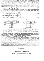
Thanks! Interesting paper. It's funny that the circuit in Fig 33c is series-applied negative feedback, completely different from what everybody is calling "Schade" feedback (parallel applied negative feedback). Being series applied, Fig 33c increases input impedance.
All good fortune,
Chris
All good fortune,
Chris
And so the transformer coupling makes all the difference and that circuit can be driven with a normal signal tube.
Yes, it's functionally equivalent to feedback to the output valve's cathode(s).
All good fortune,
Chris
All good fortune,
Chris


That Schade paper is primarily covering the development of the beam power output tube.
The concept was invented & patented in England in the 1930s. At the time it was called the 'Critical Distance Tetrode',
Money was short at Hivac, a deal was struck with RCA & some patent trading, the project came to the US.
Only the last few pages of that Schade paper do anything at all with FB. There must be somewhere another paper
by Schade covering that subject in the form named for him. But that kind of thing must have been well known,
having been already covered in detail by HS Black of Bell Telephone Labs in 1934.
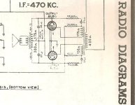
The PP 6L6 example given actually appears in a 30s home receiver. The only receiver in the entire Beitman's
Radio Diagrams, 1926-1938. That connexion is easy to drive. And its local, so the 6L6s really do look a bit like triodes.
For the curious a very good account covering the progression of 4-electrode audio tubes is at-
https://en.wikipedia.org/wiki/Tetrode#The_superheterodyne_receiver
The concept was invented & patented in England in the 1930s. At the time it was called the 'Critical Distance Tetrode',
Money was short at Hivac, a deal was struck with RCA & some patent trading, the project came to the US.
Only the last few pages of that Schade paper do anything at all with FB. There must be somewhere another paper
by Schade covering that subject in the form named for him. But that kind of thing must have been well known,
having been already covered in detail by HS Black of Bell Telephone Labs in 1934.
The PP 6L6 example given actually appears in a 30s home receiver. The only receiver in the entire Beitman's
Radio Diagrams, 1926-1938. That connexion is easy to drive. And its local, so the 6L6s really do look a bit like triodes.
For the curious a very good account covering the progression of 4-electrode audio tubes is at-
https://en.wikipedia.org/wiki/Tetrode#The_superheterodyne_receiver
Attachments
Easy? It depends on the perspective. As it was presented, it might be easy to drive for PA applications, not easy for HiFi because an interstage transformer that has all the burden of phase splitting, high signal delivery with reasonably high inductance + the DC current flowing into the primary is not going to be easy at all. Very few transformers of this type EVER made can do that with reasonable bandwidth at reasonable distortion across the audio band and for sure they are not cheap. Most IT's are either decent at low-medium frequency but inevitably introduce significant distortion already from few KHz's or do decently at higher frequency but are poor at low frequency. Either way they are always short of something.That connexion is easy to drive. And its local, so the 6L6s really do look a bit like triodes.
If I were to do it I would drive it with a PP driver, no DC into the IT transformer and move the phase splitting upstream towards the input.
That is not the RH84. The RH84 is like Millet's where the driver gets supply by means of standard anode resistor. Use the 6L6 with this circuit.Bode Plot of the Driver Gain on an example of Alex Kitec's RH84.
Driving a Loudspeaker Simulator. The gain of the driver varies in response to the loudspeaker impedance variation.
Besides, could you simulate the following, please?
1) disconnect the 100K fbk resistor
2) From the primary side where the plate of the output tube is connected put 27K + 27K in series across the primary.
3) Connect now the 100K resistor between the 2 resistors
The reason why I ask is that I have just found the page below digging into this forum and it seems that my idea is that wrong about feedback ratios and effective value of feedback resistor.
So what I have just asked is what you see in 7.31. 27+27K is at least 10 times 5K and the feedback factor is lower.
The puzzling thing is that if first says that
beta= A*B
A = R/R+Rfbk (RL in the description) where R=ra//Rg
B=R1/R1+R2
Then the effective value of the feedback resistor is RL/(beta*A+1) where now beta has magically become R1/R1+R2.....
Then circuit you have just simulated in post #137 would be with R2=0 and R1>>5K, including infinite....
Attachments
- Home
- Amplifiers
- Tubes / Valves
- Simple ECL86 amp