ECL82 SE Amp John L Stewart
Lots of talk & speculation, it’s time to have a look at the performance we might expect from such an amp. For this set of simulations I’ve used images for triodes & pentodes someone new might not be familiar with. But they were & are still commonly used in texts of EE. For both toobz & SS devices. This kind of simulation leaves all the DC calcs out & concentrates on what a circuit will do to the first order. Considering the variability of toobz on today’s market that should work very well to predict what the final result will be. And it helps a lot to avoid dead ends.
In summary, a triode may be replaced in an AC circuit by an inverting voltage controlled generator of value ‘mu’. And a series resistor of ‘rp’.
Similarly, a pentode may be substituted in a circuit with a voltage controlled current generator of ‘ma / V’…..milliamps per volt…………………..gm. And a parallel resistance ‘rp’.
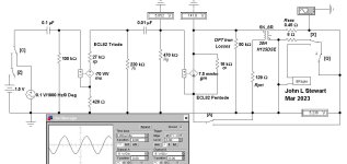
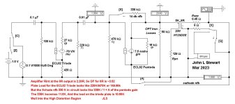
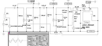
For the ECL82 in the simulation the specs are taken from the Brimar data sheet.
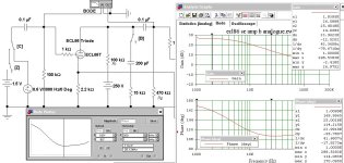
The OPT is a Hammond 125DSE, something that won’t break the bank. I’ve measured the DCR of both primary & secondary windings & estimated iron core loss. That way a realistic estimate of cct performance is possible including the OPT losses.
There are several switches in the simulation that allow various conditions to be set. In Test 1 we can see the gain of the first stage is ~50………………….. 50.52 / 0.1. In Test 2 the switch A has been set to connect NFB to the pentode from the OPT 8R tap. The NFB calcs to ~6db. Refer to the VM at the lower RHS………………………….2.599V.
In Test 3 switch Q open circuits the output, the output voltage rises to 3.942V. The internal resistance of the amplifier with CNFB applied is the change of output voltage divided by the change of current. Change of output voltage is 3.942 – 2.599………………And change of output current is ( 2.599 / 8 )………..no current at open circuit (OC). So internal resistance of the amp is ~4.14R & DF on the 8R tap is 8 / 4.14………………~1.93.
More later. 😀
Lots of talk & speculation, it’s time to have a look at the performance we might expect from such an amp. For this set of simulations I’ve used images for triodes & pentodes someone new might not be familiar with. But they were & are still commonly used in texts of EE. For both toobz & SS devices. This kind of simulation leaves all the DC calcs out & concentrates on what a circuit will do to the first order. Considering the variability of toobz on today’s market that should work very well to predict what the final result will be. And it helps a lot to avoid dead ends.
In summary, a triode may be replaced in an AC circuit by an inverting voltage controlled generator of value ‘mu’. And a series resistor of ‘rp’.
Similarly, a pentode may be substituted in a circuit with a voltage controlled current generator of ‘ma / V’…..milliamps per volt…………………..gm. And a parallel resistance ‘rp’.
For the ECL82 in the simulation the specs are taken from the Brimar data sheet.
The OPT is a Hammond 125DSE, something that won’t break the bank. I’ve measured the DCR of both primary & secondary windings & estimated iron core loss. That way a realistic estimate of cct performance is possible including the OPT losses.
There are several switches in the simulation that allow various conditions to be set. In Test 1 we can see the gain of the first stage is ~50………………….. 50.52 / 0.1. In Test 2 the switch A has been set to connect NFB to the pentode from the OPT 8R tap. The NFB calcs to ~6db. Refer to the VM at the lower RHS………………………….2.599V.
In Test 3 switch Q open circuits the output, the output voltage rises to 3.942V. The internal resistance of the amplifier with CNFB applied is the change of output voltage divided by the change of current. Change of output voltage is 3.942 – 2.599………………And change of output current is ( 2.599 / 8 )………..no current at open circuit (OC). So internal resistance of the amp is ~4.14R & DF on the 8R tap is 8 / 4.14………………~1.93.
More later. 😀
Attachments


ECL82 SE Amp Continued
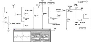
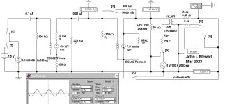
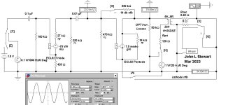
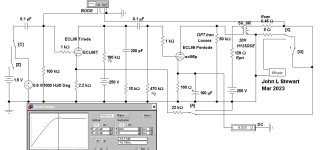
In Test 4 the 8R load is unhooked while the CNFB is disabled. The gain of the pentode increases toward its mu, that being for a pentode a rather high number. The only damping is the OPT iron losses & the parallel resistance of the pentode itself. The internal resistance of the amplifier can be calculated same as it was with CNFB.
So voltage difference is (18.26 – 5.236 )V & current difference is 5.236A. And Rint is 19.90R………………..while DF is 8 / 19.9………………………………~0.4. Not much damping there but typical of pentodes without some voltage NFB.
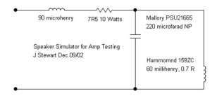
Tests 5 & 6 show how increasing the amplifier DF helps improve the transient response. A circuit to simulate a typical 8R loudspeaker is substituted for the 8R resistor load (Switch X). Without NFB the 1.5V step function applied at the amp front end (Switches C & Z) causes a very large overshoot at the output. With the CNFB applied (Switch A) the signal is well damped.
If an ECL86 / PCL86 were sub’d into the test circuit the bottom line would not be much different. For a build the decision often comes down to what is available. Or personal preferences.
More later, various NFB schemes, what are the trade offs, how effective are they. 😀
In Test 4 the 8R load is unhooked while the CNFB is disabled. The gain of the pentode increases toward its mu, that being for a pentode a rather high number. The only damping is the OPT iron losses & the parallel resistance of the pentode itself. The internal resistance of the amplifier can be calculated same as it was with CNFB.
So voltage difference is (18.26 – 5.236 )V & current difference is 5.236A. And Rint is 19.90R………………..while DF is 8 / 19.9………………………………~0.4. Not much damping there but typical of pentodes without some voltage NFB.
Tests 5 & 6 show how increasing the amplifier DF helps improve the transient response. A circuit to simulate a typical 8R loudspeaker is substituted for the 8R resistor load (Switch X). Without NFB the 1.5V step function applied at the amp front end (Switches C & Z) causes a very large overshoot at the output. With the CNFB applied (Switch A) the signal is well damped.
If an ECL86 / PCL86 were sub’d into the test circuit the bottom line would not be much different. For a build the decision often comes down to what is available. Or personal preferences.
More later, various NFB schemes, what are the trade offs, how effective are they. 😀
Attachments

Sorry, I'm probably confusing you even more. R6 goes between 2 and 8, R5 goes from 8 to groundNo, it goes to pin 2 along with R5. It should be as per my last effort with redrawing the schematic.
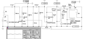
Adding Schade FB by the Cut & Try Method
This circuit is a great example of what happens when a toob amp is designed & built while ignoring the realities of physics & circuit design. It starts out looking reasonably good but then crashes & burns.
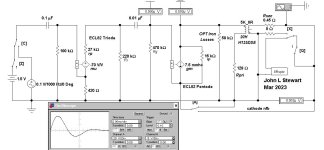
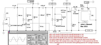
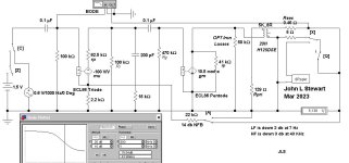
The calcs are all summarized on the schematic this time to be easily reviewed. Starts out with the Rint, Internal Impedance of the amp at the OPT 8R terminal measuring ~2,28R, so DF is ~3.52. That is a respectable number & better than most well designed SE triode Amps.
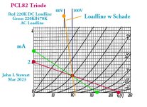
The plate load for the triode looks like 220K in parallel with the following 470K grid resistor, so looks like 149.86K. Bur the 330K Schade FB resistor is also part of that load. Since it feeds back from the following pale it looks like 330K/ A+1 of the pentode, that would be 11.5K. Now the triode plate looks like 10.68K.
That plate load is significantly less than the plate resistance of 27K…rp. Well into a region of high distortion. The 6A3 D% vs RL is generic, it applies to all common triodes.
But wait, is the triode rp really 27K? Probably not, that rp depends on a significant plate current not possible in this cct without a change in the triode Rl of 220K.
This is one of my personal objections to the use of Schade NFB. There is yet another to be covered in the next exciting episode.
This circuit is a great example of what happens when a toob amp is designed & built while ignoring the realities of physics & circuit design. It starts out looking reasonably good but then crashes & burns.
The calcs are all summarized on the schematic this time to be easily reviewed. Starts out with the Rint, Internal Impedance of the amp at the OPT 8R terminal measuring ~2,28R, so DF is ~3.52. That is a respectable number & better than most well designed SE triode Amps.
The plate load for the triode looks like 220K in parallel with the following 470K grid resistor, so looks like 149.86K. Bur the 330K Schade FB resistor is also part of that load. Since it feeds back from the following pale it looks like 330K/ A+1 of the pentode, that would be 11.5K. Now the triode plate looks like 10.68K.
That plate load is significantly less than the plate resistance of 27K…rp. Well into a region of high distortion. The 6A3 D% vs RL is generic, it applies to all common triodes.
But wait, is the triode rp really 27K? Probably not, that rp depends on a significant plate current not possible in this cct without a change in the triode Rl of 220K.
This is one of my personal objections to the use of Schade NFB. There is yet another to be covered in the next exciting episode.
Attachments

That all goes way over my head jhstewart9! But hopefully I'll come back to it one day and it will make sense 😁.

Summary of ECL86 SE Amps John L StewartThat all goes way over my head jhstewart9! But hopefully I'll come back to it one day and it will make sense
The Amp in #1 is a safe build, no NFB or other complications to create problems. But the pentode as an output with no NFB will have very little damping of the loudspeaker, typical of all common pentodes. There is a simple fix that takes care of the Damping Factor of pentodes.
The Amp in #28 looks OK. But fixed bias should be avoided like the plague, as the tubes age their operating point will continually shift. OK if you want to waste your time taking voltmeter measurements to be sure the tubes are OK. Dumping fixed bias simplifies the power supply as well. But each cathode needs its own bias resister & electrolytic bypass capacitor. DF is still poor but easily fixed.
The Amp in #29 is similar to the previous with the exception the pentode is now triode connected. So that a much better DF results. But less audio power is available. Also cathode biasing, not fixed should be used.
The Amp in #34 has many Warts & that is what attracted it me too it. I figured one diagram with many switches could cover most possibilities. So here we have Schade NFB included, often creates a disaster as in this example. And Schade does cause yet another problem to be discussed. The internal cathode to cathode Positive FB also deserves a look. This is a real good cct to carefully analyzed before building.
The Amp in #41 looks very straight forward. But don’t use the UL / Trode switch on the OPT with the amp powered up. The loudspeaker will respond with a loud bang. And the switch contacts could fail if an arc develops due to OPT inductance.
The DF on this one looks reasonably good, the transient response would look very similar to the eatlier example where CNFB was applied.Do you have a transient response for that jhstewart9
More to go, we will take a look at how Schade treats PS ripple. With an example. Not just talk. 😀
By popular request here is the transient response with & wo the Schade NFB.Do you have a transient response for that jhstewart9 ?
Take note of the 40:1 vertical scale change on the scope. Time scale is unchanged. 👍
Attachments


Schade NFB Increases PS Hum at the Speaker Terminals.
In this example about 10 db. Might be a problem if you are a critical listener
Why invite the problem in the first place? Another reason to avoid Schade NFB.
There are better ways to get to where we want to be. All well known.
I'll put something in that works for the OP in the next day or so. Busy here, doing who knows what!😀
Attachments
Mine too. With cathode feedback instead there is no such additional load and anything attached in front of the power tube control grid will be multiplied by the feedback factor. The quick explanation to this is that a tube with cathode feedback is effectily a partial cathode follower......cut.... Bur the 330K Schade FB resistor is also part of that load. Since it feeds back from the following pale it looks like 330K/ A+1 of the pentode, that would be 11.5K. Now the triode plate looks like 10.68K ....cut...
This is one of my personal objections to the use of Schade NFB.
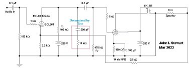
Here is a first pass on a dead simple ECL86 / PCL86 based SE amp.
The main points are summarized in the red text on the schematic. There is an error on line 3, pls cross out '220K'.
A schematic in ordinary form to be added soon as I get time. 😀
The main points are summarized in the red text on the schematic. There is an error on line 3, pls cross out '220K'.
A schematic in ordinary form to be added soon as I get time. 😀
Attachments
Here is the result of all those calcs as close as makes sense since the OPT will make a significant difference.I am hoping to build a small SE valve amplifier as a project.
Using the Hammond 125DSE as the OPT results in 3 db down at 7 Hz.
The HF RC frequency step is best determined experimentally, using a scope & square wave generator.
Otherwise just use the parts on the schematic as a start.
The circuit with the H125DSE is down 3 db at 43 KHz.
As I've said in the past the Electronic Workbench (EWB) I use was developed in 1995, long after tubes were out of style.
The result is that there is no easy way to stuff in pentode models. The way out is to use another common technique as you
have seen in the calculations. These result in very good predictions of circuit performance, And still used in SS design.
For the inquisitive the Bode Plot of both the complete amp & the HF freq step are included. The freq step is plotted
with the NFB unhooked so that this part of the cct is isolated.
The 250V supply might be pushing the plate dissipation a bit, something to watch for. The HT may have to be reduced.
Could also try increasing the pentode cathode resistor to 200R. 👍
Attachments
PS Immunity
Application of NFB on this Amp results in reduction of PS Hum in the Audio Output.
The reduction in this case ~13 db, about the same as the FB factor as we would expect.
These results depend on a well filtered screen supply, whether Schade FB of Full Loop. 👍
Application of NFB on this Amp results in reduction of PS Hum in the Audio Output.
The reduction in this case ~13 db, about the same as the FB factor as we would expect.
These results depend on a well filtered screen supply, whether Schade FB of Full Loop. 👍
Attachments
Thank you John.
I'm keeping your analysis in my library.

I have a better visual understanding of why many object to the RH Amplifier topology.
So a pentode is much preferred here.
So the triode is used as input then cut a hole for pentode.
I think I'll go with that one

I'm keeping your analysis in my library.
I have a better visual understanding of why many object to the RH Amplifier topology.
So a pentode is much preferred here.
So the triode is used as input then cut a hole for pentode.
I think I'll go with that one
The RH amplifier is not as bad as that in terms of load impedance. If it were as bad as above there would be no discussion about triode or pentode driver....
Besides, if you ground the positive of the secondary and connect the negative directly to the cathode you will get about 5 dB local fbk without the need of compensation and other stuff that only degrade the sound. No overall feedback will be necessary.
The PCL86 is more convenient not just for the cost but also because it could be used with fixed bias without additional secondaries....you can derive the bias in parallel from 13V AC heater supply. Plenty of filtering and voila'. You can use prettly large capacitors as current draw is small and won't load the PSU transformer much. Works fine. I have also put a partition at the input because it was too sensitive. For the rest pretty much the same as above.
This is my bench amplifier for listening to the radio. I will post a picture later when I get home.
Need to know the frequency of the ripple & it's peak to peak voltage to design a suitable filter.I understand that in order to use the DC HT supple from the boost converter with the schematic bellow, some more work be required before the 1k resistors to remove ripple.
Have you got the published specs for the convertor, like maybe a data sheet? 👍
Only if we ignore reality. For an example of Alex Kitec's RH84, I get the following-The RH amplifier is not as bad as that in terms of load impedance
Driver DC Loadline is 22k.
Driver AC Loadline is 22Kll470K or 21.02K
The EL84 / 6BQ5 gain is ~ Gm*Rl...............10 ma/V * 5K................................~50
The looking back resistance of the Schade 100K resister is ~2K
And the final load on the driver is 1.83K 😱
Does anybody ever put a Scope & SA on these amps to see whats happening?🙄
- Home
- Amplifiers
- Tubes / Valves
- Simple ECL86 amp