They are different metrics for the same imperfection. Which one is convenient depends on the circumstances.
For example, suppose you are working on some system that is particularly sensitive to phase noise at offset frequencies between 200 kHz and 400 kHz (for example an FM radio that has to receive a weak signal while there is a large interferer 300 kHz away). Describing the timing uncertainty of the oscillator signal as phase noise, you can just specify how low the phase noise needs to be in this particular offset frequency range. Describing it with any of the usual jitter metrics, you can't.
For example, suppose you are working on some system that is particularly sensitive to phase noise at offset frequencies between 200 kHz and 400 kHz (for example an FM radio that has to receive a weak signal while there is a large interferer 300 kHz away). Describing the timing uncertainty of the oscillator signal as phase noise, you can just specify how low the phase noise needs to be in this particular offset frequency range. Describing it with any of the usual jitter metrics, you can't.

Neither of those treat close-in phase noise or jitter differently. I've only seen so called SOA audio clock vendors falsely treat close-in phase noise as something not included in jitter.
There seems to be some controversy even defining what they are.
However, sure, phase noise and jitter are ways of measuring timing errors either in the frequency domain or the time domain respectively. That's always true in a general way
OTOH, if you want to measure very short time jitter that is equivalent to close-in phase noise then that can be a problem. A scope with a jitter measurement package is probably going to be limited by its own time-base. So as a practical matter, measured jitter tends to have different limits than measured phase noise. And converting from measurements in one domain to the other is not always directly possible.
Last edited:
I have not seen any controversy in scientific publications.
In terms of audio jitter refers to timing instability in general, not far-out phase noise.
In terms of audio jitter refers to timing instability in general, not far-out phase noise.
That's just the problem with jitter. Close-in phase noise can have totally different effects than far-out phase noise, yet they are lumped together in one jitter figure. To mitigate it a bit, there are different jitter metrics, like cycle jitter, cycle-to-cycle jitter and so on.
Yes, that may be a problem but there is still no need to create new meanings for generally accepted terminology.
And this all started by a member noting "CPLD on the I2SoverUSB introduces jitter". That clearly was not meant to refer to far-out phase noise but timing instability in general.
And this all started by a member noting "CPLD on the I2SoverUSB introduces jitter". That clearly was not meant to refer to far-out phase noise but timing instability in general.
It's nice to present the new firmware.
First of all, I'd like to thank Markw4 for your help!
The entire software is practically completely new.
The first FIR filter now has x8 fixed interpolation (fs 44.1kHz - 192kHz), has 2048 taps, 32 bit coefficients and 100dB stopband attenuation.
Then it's a two-stage CIC filter and it's oversampled to the final x256. Oversampling depends on the rate of incoming data.
Then we have a 5-order sigma delta modulator, which has classical CRFB structure, with noise shaping and dithering.
And as before, at the end the dsd streams are time aligned using ODDR2 primitives.
We made tens of different firmware configurations and finally chose this version after listening sessions.
DIY use only!
Attachments
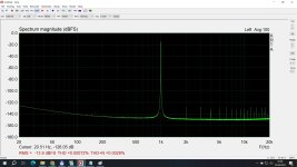
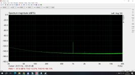
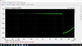
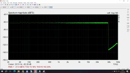
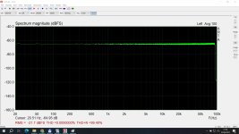
And now some measurements.
These measurements are with DSC 2.5.2
These measurements are with DSC 2.5.2
Attachments


A number of prospective FPGA firmware versions were auditioned over multiple listening session. The new release version 3 was deemed overall best so far. We feel SQ is good enough that it could likely be used in a moderately high end commercial dac. Quite an accomplishment fitting it into a low-cost FPGA of that size.
When using the FPGA converter it does help to keep the PCM volume level in the computer up for best SQ (but maybe not so high as cause intersample overs). There are modern perceptual VU meters which be used to find reconstructed peak levels of wav files in order to check for intersample overs, if desired. Rather than use digital volume control, we have been using an analog line amp with volume control after the dac. Keeps the DSD converter working at its best SNR/DNR.
As always, minimizing conducted and radiated EMI/RFI, including avoiding ground loops wherever possible can make a substantial difference in terms of final SQ.
Last edited:
To clarify, just speaking for some of the folks here where I am, in Auburn. Not speaking for the two designers.We feel SQ is good...
Maybe I should also say that what we did where I am included comparing sound of version 3 firmware with SACD rips played on the same dac. Sound stage seems better at DSD256. OTOH, there is a bit of openness in SACD midrange frequencies where version 3 firmware may not quite have the same. Maybe its that they sound a little different in the balance between midrange openness and sibilance at a bit higher frequencies.
I wish works better, I want to do PEQ in PCM for DCR. Old firmware is not close of sound quality to the original natives DSD64 files. I guess could be more important the filter than go for DSD256, so if you go for DSD64 or 128 for sure you have more space at the FPGA to do that.
Also not my cup of tea comparing vs SACD.
I'm comparing exactly the same record in PCM upsampled with pcm2dsd vs native DSD64.
Also the bypass function for native DSD degrades the sound quality....
Also not my cup of tea comparing vs SACD.
I'm comparing exactly the same record in PCM upsampled with pcm2dsd vs native DSD64.
Also the bypass function for native DSD degrades the sound quality....
Last edited:
Merlin,
Why don't you try again and see if you like it better now? Do you have test files of the same music in SACD and WAV formats?
Why don't you try again and see if you like it better now? Do you have test files of the same music in SACD and WAV formats?
- Home
- Source & Line
- Digital Line Level
- Simple DSD modulator for DSC2