Re: Re: Re: Re: The circuit which started it all, for me...
Tarun
Does this mean that it might be a good idea to permanently change R10 from 330 to 150 Ohms? (I know that most preamps never carry 3V signals, but then load impedances can sometimes go below 10KOhms.)pjacobi said:Generally speaking: Yes, of course. You'll need a comfortable ratio of Iq to output current, to get these low numbers....
But for driving 3Vrms, you better change Iq to 5mA by changing R10 to 150. Then the numbers are fine again:
Tarun
Any mods you suggest, Hugh?
After all this feedback, now I'm certain I'll build a small prototype and actually listen to this, and compare it with an NE5532 buffer. What's more, I'll keep the PSU the same for both. Just don't lynch me if I can't hear any diff. 🙂
Tarun
Thanks for the comments. Any suggested mods, like the R10 value reduction, or anything else?AKSA said:I've not seen this Elektor design before; it is a most impressive topology...
After all this feedback, now I'm certain I'll build a small prototype and actually listen to this, and compare it with an NE5532 buffer. What's more, I'll keep the PSU the same for both. Just don't lynch me if I can't hear any diff. 🙂
Tarun
What does this change do?
Dear Peter,
Tarun
Dear Peter,
Please can you explain to clueless newbie what this replacement of two BJTs with two FETs achieves? I'm really new to all this, so I can't quite figure it out. And will your design also have the same 0.7V DC output offset as the original Elektor one?pjacobi said:Please be so kind and have look at this modification of the Elektor circuit...
Tarun
Re: What does this change do?
The Elektor circuit has no offset, as it is capacitor coupled. The modified circuit as drawn has 0.7V offset and an output capacitor has to be added.
The two BJTs which work in common-base mode were replaced by JFETs.
For the upper one, this allows the elimination of the C2 (and R3/R4/R5). A slight simplification at the cost of more expensive active device, which most likely must be selected for the right Idss.
For the lower one, it increases the impedance of the constant current source, makes it more constant. (Warning, silly sim results ahead: from 14MOhm to 100MOhm). Giving a typical load of 10k, this is of course next to meaningless.
Also, whatever this relates to reality, the simulation results are even better than for the original.
To at least attempt clarifying my intention, I was trying a hommage to the original circuit. Which (IMHO) in an epoche specific way aimed for an "ideal" buffer. I wanted to suggest and ask, whether this can even better achieved by a mix of BJTs and JFETs.
Best Regards,
Peter Jacobi
tcpip said:
Please can you explain to clueless newbie what this replacement of two BJTs with two FETs achieves? I'm really new to all this, so I can't quite figure it out. And will your design also have the same 0.7V DC output offset as the original Elektor one?
The Elektor circuit has no offset, as it is capacitor coupled. The modified circuit as drawn has 0.7V offset and an output capacitor has to be added.
The two BJTs which work in common-base mode were replaced by JFETs.
For the upper one, this allows the elimination of the C2 (and R3/R4/R5). A slight simplification at the cost of more expensive active device, which most likely must be selected for the right Idss.
For the lower one, it increases the impedance of the constant current source, makes it more constant. (Warning, silly sim results ahead: from 14MOhm to 100MOhm). Giving a typical load of 10k, this is of course next to meaningless.
Also, whatever this relates to reality, the simulation results are even better than for the original.
To at least attempt clarifying my intention, I was trying a hommage to the original circuit. Which (IMHO) in an epoche specific way aimed for an "ideal" buffer. I wanted to suggest and ask, whether this can even better achieved by a mix of BJTs and JFETs.
Best Regards,
Peter Jacobi
Re: Re: Re: Re: Re: The circuit which started it all, for me...
Sorry, complete confusion by sloppy writing of me.
A) The standing current can be increased from 1m to 5m by changing R9 from 820 Ohm to 150 Ohm.
B) From a strictly subjective feeling, I'd go for 3mA...5mA in this buffer. If you build it, you can easily let the experiment decide.
Regards,
Peter Jacobi
tcpip said:
Does this mean that it might be a good idea to permanently change R10 from 330 to 150 Ohms? (I know that most preamps never carry 3V signals, but then load impedances can sometimes go below 10KOhms.)
Sorry, complete confusion by sloppy writing of me.
A) The standing current can be increased from 1m to 5m by changing R9 from 820 Ohm to 150 Ohm.
B) From a strictly subjective feeling, I'd go for 3mA...5mA in this buffer. If you build it, you can easily let the experiment decide.
Regards,
Peter Jacobi
With regards to the fet subsitutions in the Elector buffer, cascoding the current source with a fet is fine, but pretty irrelevant to distortion performance when driving any load that requires buffering – the Ic modulation of the pass transistor Vbe will dominate
Replacing the bjt cascode of the pass transistor with a fet is less likely to improve distortion – the fet will have a much larger source impedance than the bjt cascode and any pass transistor current variation from driving a real load will give more variation at the pass transistor Vcb than the bjt approach
As long as we’re talking simple buffers, a simple way to reduce Vbe modulation (after increasing bias current to the max) is to use the compound feedback pair structure
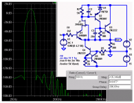
Below I show a “simple” elaboration of the single stage buffer using a compound feedback triple (Q1-3) biased with a feedback current sink (Q4,5)
(the circuit sims ok but is certainly too simple for the real world, compensation and cap load stability need some elaboration)
Replacing the bjt cascode of the pass transistor with a fet is less likely to improve distortion – the fet will have a much larger source impedance than the bjt cascode and any pass transistor current variation from driving a real load will give more variation at the pass transistor Vcb than the bjt approach
As long as we’re talking simple buffers, a simple way to reduce Vbe modulation (after increasing bias current to the max) is to use the compound feedback pair structure
Below I show a “simple” elaboration of the single stage buffer using a compound feedback triple (Q1-3) biased with a feedback current sink (Q4,5)
(the circuit sims ok but is certainly too simple for the real world, compensation and cap load stability need some elaboration)
Attachments
simple is as simple does........
"With regards to the fet subsitutions in the Elector buffer"
So much for being a simple buffer any more........
The idea for using Jfets for the upper transistor in the cascode was to use the gate to source voltage at the quiesent current to get rid of the
need for the bias network. Cascoding the current source is most likely for the increase in power supply rejection for noise on the negative supply rather than the than reducing the parallel load impedance the follower has to drive. Adding a compound circuit for Q1 seems to be a waste of parts if you add another follower Q3 driving 300 ohms! I don't quite understand why everyone seems to be allergic to capacitors when it comes to filtering the reference voltage. A cascode for the current source is pretty useless if the current is going to move around from noise in the reference voltage from noise in the negative power supply.
DON'T QUIT YOUR DAY JOB.
Yes the simple EF buffer can be improved but what's really wrong with it in the first place, what needs fixing? A tiny amount of low order distortion proportional to the input signal, don't see much to worry about there.
fred, put on your glasses
i thought it was pretty clear R6 = 300 Ohms is the load, seemed (somewhat) more useful than printing out distortion # for "improved" emitter followers with 330K "load" resistors - a buffer otta BUF, and 300 Ohms is a real test of a line level buffer, in fact i could probably shop the idea over at headfi as a discrete buffer for the Senn HD600
Q3 (and Q2) are inside the feedback loop formed by Q1 which is acting as the input stage of a "current feedback" amplifier, Q2 is also servoing Q3, the whole being used as single compound transistor "emitter follower" - i know you can recognize a "triple" output stage in a power amp
btw the Q4/5 current sink does provide a fair amount of psrr, splitting R5 and adding a bypass cap to V- wouldn't hurt though
i know the fet cascode is elegant and it works pretty good if the current is nearly constant (see J1 cascoding my input Q1), but in the pass transistor the collector current is going to vary and cause a dynamic V drop at the fet source, reducing the effectiveness of the cascode
Hi,
Yeah...No point in adding yet another wobbler, I'd say...
Geez...Is it really THAT hard to grasp?
Seems like it,😉
A cascode for the current source is pretty useless if the current is going to move around from noise in the reference voltage from noise in the negative power supply
Yeah...No point in adding yet another wobbler, I'd say...
Geez...Is it really THAT hard to grasp?
Seems like it,😉
"simple" certainly has a range of definitions, the intermediate step with the simple 2 transistor cfp can be seen in:
http://www.dself.dsl.pipex.com/ampins/discrete/cfp.htm
http://www.dself.dsl.pipex.com/ampins/discrete/cfp.htm
Yes, JCX, my very point, figure 11 in fact, in Self's site.
Figure 13 is the SS equivalent of a White Cathode Follower, and that appeals too, though the PSRR is poor. I have tried it and it definitely gives equivalent sonics and output for about half the quiescent.
RichardC from Nottingham made the reasonable point that a simple, SE follower's distortion would be essentially lower order harmonics anyway, and why improve on that, particularly as most of the distortions introduced by digital electronics are completely non-musical in nature......
Cheers,
Hugh
Re: The circuit which started it all, for me...
And tell me... C1 and C3 can be larger, right? They're just DC blocking caps, aren't they? In that case, I can use whatever good quality larger-value caps I can find, maybe in the 1-2.2uF range?
Tarun
Thanks for the patient explanation. I don't think I understood everything, but I'll keep re-reading these posts for some time. 🙂pjacobi said:The Elektor circuit has no offset, as it is capacitor coupled. The modified circuit as drawn has 0.7V offset and an output capacitor has to be added....
Thanks once again. Will remember to fiddle with R9 when I build it. And I'll let you know.A) The standing current can be increased from 1m to 5m by changing R9 from 820 Ohm to 150 Ohm.
B) From a strictly subjective feeling, I'd go for 3mA...5mA in this buffer. If you build it, you can easily let the experiment decide.
And tell me... C1 and C3 can be larger, right? They're just DC blocking caps, aren't they? In that case, I can use whatever good quality larger-value caps I can find, maybe in the 1-2.2uF range?
Tarun
Richard C said:Yes the simple EF buffer can be improved but what's really wrong with it in the first place,
its "fault" is its simplicity. It seems to me that some of us don't care much about how good / bad it sounds.
No, Millwood, you know better than that. You expect some performance from a buffer, after all there MUST be a reason why you want it, to make the system sound better, no?
The simple EF doesn't do too well on that performance, and can be improved. Which makes it no longer simple, of course. But you get what you pay for, and vice versa.
Jan Didden
The simple EF doesn't do too well on that performance, and can be improved. Which makes it no longer simple, of course. But you get what you pay for, and vice versa.
Jan Didden
millwood said:
its "fault" is its simplicity.
You've lost me there😕
Millwood, what in your opinion is wrong with the 'sound' of the simple buffer?
I don't think it's a sound issue, just that a simple EF is so simple it's boring, and certainly not much to discuss.
As a side note: Some 20+ years ago, I put a battery powered EF buffer in a DIY electric guitar, and it certainly improved the sound, to put it mildly. Now, maybe my amp at the time was crappy, but still, that buffer was the most effective treble booster I've ever come across.
Rune
As a side note: Some 20+ years ago, I put a battery powered EF buffer in a DIY electric guitar, and it certainly improved the sound, to put it mildly. Now, maybe my amp at the time was crappy, but still, that buffer was the most effective treble booster I've ever come across.
Rune
Richard C said:
You've lost me there😕
Millwood, what in your opinion is wrong with the 'sound' of the simple buffer?
the emphasise is on "fault", 🙂
- Status
- Not open for further replies.
- Home
- Source & Line
- Analog Line Level
- Simple discrete unity gain buffer