As I understand it, the published circuit uses 4x 2SK170 for the diff pair.
As to To, it is indeed a degenerated CCS. One can argue one can use any FET with the right Idss.
But the author was already using K170 for T1, so without digging too deep, I asuume he had good reason to use 2N6550.
The nearest FET I can find with similar Yfs, low noise & Ciss, ... is 2SK117.
And it is very easy to get, arguably easier than 2SK170v.
Patrick
I just happen to have a bunch of k170v which I'd try first, changing the value of R_0 to make sure it works well with the pairs above. A bf862 might also work well in that position (high gm, low noise, low capacitance).
Both of those have a much higher Yfs and you end up with a lowish Ro, which means less degeneration and hence less stability.
All theory of course.
But yes, why not try it first,
Patrick
All theory of course.
But yes, why not try it first,
Patrick
Both of those have a much higher Yfs and you end up with a lowish Ro, which means less degeneration and hence less stability.
All theory of course.
But yes, why not try it first,
Patrick
Patrick are you sure, these are the values I get from data sheet.
gm min max typ
2N6550 25mS N/A 150mS
BF862 35mS 45mS N/A
2sk117 4mS 15mS N/A
2sk170v N/A 22mS N/A
Idss min typ max
2n6550 10mA 100mA 250mA
BF862 10mA N/A 25mA
2sk117 1.2mA N/A 14mA
2sk170v 10mA 13mA 20mA
The BF862 and the 2sk170 are specified differently when giving gm
Look at the graphs of typical values and you see that they are very similar gain when measured at similar Id.
The BF862 is specified for HF whereas the sk170 is specified for audio frequencies. I think this may make a big difference to the LF noise specs.
Look at the graphs of typical values and you see that they are very similar gain when measured at similar Id.
The BF862 is specified for HF whereas the sk170 is specified for audio frequencies. I think this may make a big difference to the LF noise specs.
referring to Syn's post85?
I do not think my interpretation is at odds with Syn's measured noise.
I do not think my interpretation is at odds with Syn's measured noise.
I think the current source is not super-critical. BTW this could probably be used as a MC headamp too? The purists would dismiss the ferrites, but at these levels there should be no issues. I posted Quantec plots (and a picture for JC's benefit🙂 )for the BF862 in the PASS forum 2.5nV @ 10Hz/5mA and ~.7nV or so at 100kHz.
EDIT - Epcos has a very nice inductor design app-note on their site, I found it here - www.thierry-lequeu.fr/data/AN-EPCOS.pdf
EDIT - Epcos has a very nice inductor design app-note on their site, I found it here - www.thierry-lequeu.fr/data/AN-EPCOS.pdf
Last edited:
You are right. I misread 150mS as 15mS.
So maybe use 10x 2SK117 in parallel. Surely lower noise, about same Idss and Yfs as single 2N6550.
I am a bit concerned that the circuit as published requires a very low source impedance (0.5R). Do you think you can load a MC cart with it ? I mean do most low current power supplies or cap multipliers have such low impedance ?
A friend of mine with a Ph.D. in electromagnetism promised to see if he can redesign the transformers based on the 36x22 core, in the next couple of weeks.
Patrick
I am a bit concerned that the circuit as published requires a very low source impedance (0.5R). Do you think you can load a MC cart with it ? I mean do most low current power supplies or cap multipliers have such low impedance ?
Patrick
There have been several articles over the years about using a virtual short as input for MC or ribbon mic. I find the claims of self damping to be a little hard to believe but the principle is sound for amplifying the signal.
I can believe in the self damping story, but I also read that different cartridges have different optimum load. So virtual short may not be good for all ??
And if not, how to cure ? Change the Tx design to suit the source ?
Patrick
And if not, how to cure ? Change the Tx design to suit the source ?
Patrick
Would distortion be a factor at all with a ferrite input transformer? I know there are some materials like 3E55 which is labeled as low THD, with DSL applications.
I know next to nothing about this, but I have a sense that it's more complicated than just having to do with the signal amplitude. Have a look at page 4 of this
http://www.ferroxcube.com/appl/info/DSL.pdf
http://www.ferroxcube.com/appl/info/DSL.pdf
Would distortion be a factor at all with a ferrite input transformer? I know there are some materials like 3E55 which is labeled as low THD, with DSL applications.
The DSL transformers are very small and must be sized for THD at low frequencies just like audio transformers (just not as low). The power density is rather high. This application is more like mic output transformers, but the levels here are even lower.
Yes, .065nV makes no sense at 20 Ohms DC R. I have not totally figured out those low frequency peaking issues.
I'm highly sceptical about a transformer based approach. The output impedance of a power supply can be very complex and it is difficult to quantify--let alone verify--the resulting frequency response. The errors from incomplete modelling of this effect likely outweight the possible voltage noise advantage by a considerable margin.
It all gets back to what I've said in some similar thread: you have to know what you want measure. What is the expected noise of the power supply? What's the output voltage, what the output impedance? Without these specifications this thread will run in cycles forever. There are a zillion possibilities to build a "low noise amplifier", and the only reasonable way to select one is by an educated decision.
I'd say it is better to build a simple, no nonsense design first and see how it keeps up in daily lab use. After you've gained more experience in what you really need you can go on with a more specific design.
Samuel
I don't disagree Samuel, but it's fun to explore other ideas.
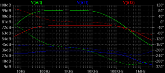
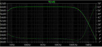
As for simple discrete, which I was still hoping for, I built the attached circuit last night. Without feedback the first and second stage behave almost identical to the simulation. But as soon as the third stage and feedback are attached, I get these square steps up to the rails. I don't really understand why; the simulation shows a good phase margin of more than 80 degrees.
As for simple discrete, which I was still hoping for, I built the attached circuit last night. Without feedback the first and second stage behave almost identical to the simulation. But as soon as the third stage and feedback are attached, I get these square steps up to the rails. I don't really understand why; the simulation shows a good phase margin of more than 80 degrees.
Attachments
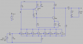
Forgot to say, but I built syn08's circuit too (with k270v), and it didn't work for me, it oscillated wildly. Almost the same thing as this discrete example, without feedback the first stage worked fine, but as soon as the second stage plus feedback was added, boom! Built it three different times to make sure I didn't make a mistake in wiring.
- Home
- Amplifiers
- Solid State
- Simple 60dB discrete low noise amplifier (lna)