Is the circuit stable ? You could try a 2Mohm resistor from Pin2 to Pin6 of your opamp with a 15pF cap across it.
I think the capacitor is supposed to bypass the LED noise. The circuit is stable, except for a low resistance (say 10 ohms) across the input. I did put a 1meg resistor bypassed by a 47pF and that solved the problem. A servo wouldn't work unless I refer the input to a middle voltage, and I don't want that, because I'd lose 1/2 the working voltage on the jfets.
Two 12V lead acid batteries, in series.
And what is the decoupling capacitance you a using on the preamp circuit.
What prototyping technique are you using for this preamp, a photo would be good .
Decoupling 100u || 100n. For prototyping I don't usually make a pcb, just solder the parts one to another, in the air, and using solid copper wire for ground and Vcc. This prototype is inside a metal cookie box, with BNC input and output. I built it at work, so when I go back I'll take a picture and post.
Decoupling 100u || 100n. For prototyping I don't usually make a pcb, just solder the parts one to another, in the air, and using solid copper wire for ground and Vcc. This prototype is inside a metal cookie box, with BNC input and output. I built it at work, so when I go back I'll take a picture and post.
Does your circuit work as expected, do you have any problems with its electronic operation.
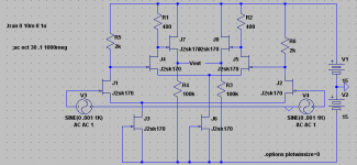
Would it work to simply cascade gain stages without any feedback? I came up with this, but of course I have no clue how exactly to work with FETs, much less any conception of how noise works.
Instead of using emitter resistors (proof that I know nothing about Jfets, I can't name the pins), a Jfet's Gm is large enough we might go without them. Then we can adjust the quiescent current to change Gm and in this way change gain.
I only now noticed this thread, wish I had found it sooner.
First stage multiplies by 50, the next one by 20 (think I got that right, but gain is at ~1000 simulated anyways)
- keantoken
Attachments
OK guys, with the feedback, you were correct and I worked it out for myself until I got convinced.
So the signal across your 1R source resistor increases when you close the loop and the signal at the drain decreases by the additional feedback degeneration? Are your 8x2SK170V random for IDSS? Its interesting that 8 can work in parallel without oscillation given no gate stoppers. Above x4 it was trouble I think I have read. Or just not preferable for THD due to increased non linear capacitance in open loop head amps? Anybody know the story?
Does your circuit work as expected, do you have any problems with its electronic operation.
Seems to work as it should, meaning it doesn't oscillate, the gain seems to be in the ballpark, etc. I haven't finished its self-noise measurements.
kt, the idea here was to get a measurement preamp with very low noise (I was aiming for lower than 0.5 nV/rtHz at 1kHz), and precise and stable gain of 60dB. I was dreaming about a simple discrete design, but hey, beggars can't be choosers, so if an opamp simplifies the whole thing without added problems, I accept it. To get very low noise the first stage should have a high gain, hence the paralleled jfets. Super linearity and super low thd are not priorities here.
@salas well, syn08 was talking about possible oscillations at 200MHz. The scope I have in the office goes only to 60MHz, but I can something that can go a lot higher than that and check next week. Of course it might be simpler to just add gate inductors just in case and be done with it.
Edit: forgot to say, but I have matched the jfets to around 13.5mA Idss. Not perfectly matched though.
It's an interesting circuit but I don't understand a few things. There is essentially no current flowing at the positive input of the LT1028A, so what's the point of the J9 current sink? It seems a divider would be quieter and more effective, with a bypass to ground. Should the input impedances to the amp be better matched? The whole amplifier (i.e., feedback network) is referenced to ground, so trying to AC reference things to the supply, say with C3, is just asking for noise. Batteries are not noiseless, contrary to popular views.
Getting a predictable accurate gain using a 1 ohm resistor is difficult because trace resistances get involved at that level. IMO, a trimmer on the 1K, as you mentioned, is probably a good idea. The quality of those feedback resistors may be critical- metal films at minimum and bulk metal foil might make a measurable improvement. I don't know if the inductance of a wire wound for the 1 ohm would matter- many very low values tend to be ww, but avoid thick films like the plague!
I'm surprised that a very small local feedback cap isn't needed around U1 for stability- how does the amp do with a square wave drive? Any ringing?
Have you looked at the various composite amplifier designs published by AD and LT in their app notes?
CH
Last edited:
Ok, I understand it a bit better- the opamp inputs need to cancel ps noise. It seems difficult to get them to track. It might be interesting to inject a signal on the ps and trim the currents and compensation for best noise rejection with temporary local feedback.
CH
CH
Hi Conrad, the schematic I implemented is nothing more than a poor hybrid of two designs. I took the second stage from Samuel's circuit
http://www.sg-acoustics.ch/analogue_audio/test_gear/pdf/lab_preamp_100x_lp_r1.pdf
and the first stage from syn08's:
http://www.diyaudio.com/forums/soli...te-low-noise-amplifier-lna-5.html#post2182865
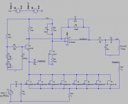
I actually changed it as per the attached schematic, with a small feedback cap and a 1meg bypassed local resistor on the opamp.
I haven't looked at particular AD or LT amplifiers (app notes), or, I have, but don't know which you refer to. However, I have looked at pretty much every low noise amplifier that I could find in journals, conferences, and on the web.
It's not a long thread, some of them were mentioned here. We (I) referenced some paper on the noise of batteries. You say they might be noisy; any particular type/conditions when that would happen?
I took some time this afternoon to do some measurements. First I dialed in the gain at 60dB, as much as I could measure it with my AC voltmeters. Then I soldered various resistors at the input and measured the output noise at 1kHz using the HP 3585A spectrum analyzer. Here are the results in nV/rtHz
Resistor Theoretical noise Measured noise
50R 0.9 1.04
1k 4.036 4.02
4k02 8.09 8
10k 12.76 12.1
10R 0.4 2.47
4R7 0.276 4.3
Something I don't understand, with very low resistances or short across the input, the noise seems to be getting larger.
http://www.sg-acoustics.ch/analogue_audio/test_gear/pdf/lab_preamp_100x_lp_r1.pdf
and the first stage from syn08's:
http://www.diyaudio.com/forums/soli...te-low-noise-amplifier-lna-5.html#post2182865
I actually changed it as per the attached schematic, with a small feedback cap and a 1meg bypassed local resistor on the opamp.
I haven't looked at particular AD or LT amplifiers (app notes), or, I have, but don't know which you refer to. However, I have looked at pretty much every low noise amplifier that I could find in journals, conferences, and on the web.
It's not a long thread, some of them were mentioned here. We (I) referenced some paper on the noise of batteries. You say they might be noisy; any particular type/conditions when that would happen?
I took some time this afternoon to do some measurements. First I dialed in the gain at 60dB, as much as I could measure it with my AC voltmeters. Then I soldered various resistors at the input and measured the output noise at 1kHz using the HP 3585A spectrum analyzer. Here are the results in nV/rtHz
Resistor Theoretical noise Measured noise
50R 0.9 1.04
1k 4.036 4.02
4k02 8.09 8
10k 12.76 12.1
10R 0.4 2.47
4R7 0.276 4.3
Something I don't understand, with very low resistances or short across the input, the noise seems to be getting larger.
Attachments
Now I like that schematic much better as it should greatly improve stability. The noise numbers certainly leave little to be desired, though I don't know about the low R increase. Quite a long while ago I measured battery noise and concluded that any benefits would be from the isolation provided, not incredibly low noise performance. I could easily build a quieter conventional supply as long as the transformer was distant, say a wall wart. About all I recall was that different battery types were very different in noise level, say alkaline vs non, that drawing current was a bad thing, and I think lead acid gel cells were the best of the bunch. I'll check the app notes, but I thought Jim Williams did something very similar with paralleled input devices on a composite amp.
CH
CH
Conrad, in post #109 of this thread
http://www.diyaudio.com/forums/soli...e-low-noise-amplifier-lna-11.html#post2191226
I posted a link to an older paper on battery noise.
Two of Jim Williams app notes are familiar to me, 83 and 124
http://cds.linear.com/docs/Application Note/an83f.pdf
http://cds.linear.com/docs/Application Note/an124f.pdf
Pheonix might be right about the oscillation, in the case of low resistance at the input. Don't know how to fix that yet, and don't know why syn08's amp, which is basically the same input stage, doesn't suffer of this.
Conrad, in post #109 of this thread
http://www.diyaudio.com/forums/soli...e-low-noise-amplifier-lna-11.html#post2191226
I posted a link to an older paper on battery noise.
Two of Jim Williams app notes are familiar to me, 83 and 124
http://cds.linear.com/docs/Application Note/an83f.pdf
http://cds.linear.com/docs/Application Note/an124f.pdf
Pheonix might be right about the oscillation, in the case of low resistance at the input. Don't know how to fix that yet, and don't know why syn08's amp, which is basically the same input stage, doesn't suffer of this.
1) He uses a small inductance on the input of the fets. I think its about 1uH air cored not shown on schematic he posted on your thread.
2) Your layout is not on a PCB his (syn08) is with a ground plane also .
Your latest schematic is ill-defined with respect to DC bias. While you might make it work by selecting some parts even slight temperature drift will make the output hit the rails. Have you tried heating the input transistors a bit (e.g. with a heat gun)?
The cascode causes the amplifier to have negative input capacitance over some frequency range. If the source has sufficiently high inductance and sufficiently low resistance the amp wil turn into an oscillator. You can fix this preferably by compensating the input Z by adding a suitable shunt element. In case of low negative capacitance a simple small capacitor (note C2 on my schematic) is usually enough. With many parallel high-C parts in the input you probably need a Zobel network. Of course there are many more instability sources, but this one will surely need your attention.
Samuel
Don't know how to fix that yet.
The cascode causes the amplifier to have negative input capacitance over some frequency range. If the source has sufficiently high inductance and sufficiently low resistance the amp wil turn into an oscillator. You can fix this preferably by compensating the input Z by adding a suitable shunt element. In case of low negative capacitance a simple small capacitor (note C2 on my schematic) is usually enough. With many parallel high-C parts in the input you probably need a Zobel network. Of course there are many more instability sources, but this one will surely need your attention.
Samuel
Last edited:
- Home
- Amplifiers
- Solid State
- Simple 60dB discrete low noise amplifier (lna)