I am pleased to report that the 100R worked out a lot better and gave me a very useful range between 9-3 with a 100K pot. However, with an 100R feed resistor, I must drive both channels with one pot. If I use one pot per channel, the shunt LDR would draw 29ma when in full throttle position, ouch.
If I use one 100R resistor, I must be very discipline to keep the pot at 9-3 position and avoid the 2 ends because a 100K pot can only sustain approx 2.4ma without violating it's power rating.
Gianni, if I were you, I would replace the 1K with 100R and try it out first. I will also suggest you to get a hold of a dual gang 250K pot as well as a 500K. My gut feeling is that one of these pots will work magic for you.
http://www.diyaudio.com/forums/showpost.php?p=1918667&postcount=2462
and
post276
show what values of LED protection resistors could be used.
They also explain why there is no point in selecting resistor to protect the high value pot from overcurrent.
One CANNOT get adequate volume adjustment range AND low pot track current. They are simply incompatible. Do not try to protect the pot. Replace it if it ever becomes faulty.
Protect the LEDS, they are the expensive bit that could be damaged if no protection resistors are used.
Each channel uses three protective resistors.
One in the 5V feed and one to each LED supply.
Gianni,
After some experimentation last night I think maybe try removing that parallel resistor you are using. I know I suggested using a series and a parallel but testing last night proves its not a great idea. It splits voltage as you had pointed out, but your last schematic shows it still in place. It does present a load and help stabilize, but my LM7805 is having no trouble keeping its voltage stable and driving only one LDR.
It might be fun to try using a trimpot parallel or a small panel mount pot parallel and then just use a resistor in series and remove 100k pot. But that would be just fun stuff, not a recommendation. We could then divide voltage and leave current to drive the LDR. Have not tried that yet. Just an idea as I was typing.
Uriah
I was simulating and showing what happens with Uriah schematic posted in this thread that i first built.but I said try the 5V feed resistor between 68r and 100r maybe even 56r, not 1k0.
Feed resistor, 100 or 1k, unbalance all the circuit, as i will explain in part 2 (the last) of my previous post; being 1k, obviously, the worst case.
Uriah, parallel resistor works very well, even if 78l05 doesn't need this, maybe 7805 do. It wont' split the voltage, unless you put it after that series resistor, whatever value it has. In the right position it will offer a small load, indipendent from what happens after it. I will demonstrate that with these "high sensitive" matched set (and only this or a matched set that works with 250k), it's possible to protect the pot having a good range from minimum to maximum. Fred, 470ohm is a perfect choice with high value ldr set or the range will be unkind. I will explain current sharing problem, ldr voltage ovedrop and why they don't work well with CCS circuit. Read my part 2, this afternoon i will post it.
Cheers,
Gianni
Uriah,
as I am able to use my system only intermittently I thought to include an indicator led to remind me to turn it off/unplug it whilst I was absent.
(why wear out the ldrs for days at a time ?)
Perhaps my inclusion of a Led (and appropriate resistor) after the 7805 is enough to stabilise the supply as you have postulated ??.
Having tried the circuit with a battery supply (4 x 1.2 volt Ni cads as you suggested) and no Led or 7805 I find I prefer the Wall wart and 7805 supply. Odd ?
Must try your 9volt and 2 x regulator version.
Cheers, Bob.
Bob,
The reason people leave it on is that the LDRs take quite a while to stabilize. So their resistance is constantly changing for a minimum of 15 minutes when first powered on. Now, I frankly dont hear the changes after the first few minutes but if you listen very closely you can detect the image moving around while they 'warm up.' In my battery version, before I loaned it out, I did turn it off when not listening. As far as what sounds better... I need to mess with supplies at some point. Swapping them in and out of the same attenuator and making notes. The one I build with batteries is a very different animal than the original Lightspeed so I am not sure what to attribute the increase in sound quality to.. batteries or build? Dont know.
Gianni,
Yeah I caught that in my head last night but figured why bother to post back about the parallel not dropping volts unless it was after the series. My jig I set up to test has the parallel after so it was stuck in my head that way when I posted.
Interested to see your circuit this afternoon! 🙂
Uriah
Bob,Uriah,
as I am able to use my system only intermittently I thought to include an indicator led to remind me to turn it off/unplug it whilst I was absent.
(why wear out the ldrs for days at a time ?)
Perhaps my inclusion of a Led (and appropriate resistor) after the 7805 is enough to stabilise the supply as you have postulated ??.
Having tried the circuit with a battery supply (4 x 1.2 volt Ni cads as you suggested) and no Led or 7805 I find I prefer the Wall wart and 7805 supply. Odd ?
Must try your 9volt and 2 x regulator version.
Cheers, Bob.
I use batteries into a single 7805 - but I use 2 of 6 volt 7ah SLA's (giving 12v) and I have no problems - like Uriah I tend to switch it off when not in use.
I had used a Wall wart (12v) into the same 7805 - I prefer the batteries.
If using 4 NiCads that gives 4.8 to 5 volts - the 7805 will not be working.
Alan
I have made a couple of Lightspeeds for practice with un-matched LDRs. I don't have much channel imbalance, although I have noticed when I turn it on the next day the image has shifted slightly and the trimmers need a bit of a tweak. Is this the real problem with un-matched LDRs?
Hi Puffin,
The problem is channels being not balanced, as in way off center and obvious. Using only a 5k trim pot I can move the image all the way across the soundstage with matched LDRs so my guess is yours are all close to each other.
Uriah
The problem is channels being not balanced, as in way off center and obvious. Using only a 5k trim pot I can move the image all the way across the soundstage with matched LDRs so my guess is yours are all close to each other.
Uriah
udailey;1926025]Bob,
The reason people leave it on is that the LDRs take quite a while to stabilize. So their resistance is constantly changing for a minimum of 15 minutes when first powered on.
Thanks Uriah, Yes, I am often away for several days and turn the system off then. When I return I am more than happy to leave on and usually give an hour or two warm up.
AlanElsdon
If using 4 NiCads that gives 4.8 to 5 volts - the 7805 will not be working.
Sorry, should have mentioned that I use a bypass switch so that the 4 NiCads go direct to the pot and the 7805 is not in circuit.
That is why I am keen to try Uriah's (and your) suggestion of using a higher battery voltage and (multiple ?) regulators.
Found an explanation and possible solutions (part 2)
Hi everyone,
i left with the story about the leds being not a "democratic" current devices.
They tend to have what they need, eating current and voltage to less hungry ones, even if they are the same devices with the same specs.
This happens when they are in parallel, just like the lsa. Problem is even worse with a pot that moves up and down and changes the current between its two legs.
Tipically, it's a common and right method to put one resistor for each led, so to avoid the unwanted interferences among them.
That's George's way, but he use a small resistor value to protect the leds, with LDR sets that show about 10k total impedance (100k pot).
I'm posting in this "500k pot LDR set" because i have these from Uriah like many of you and in this 2 posts i only talk about them.
What i read in many posts about LSA is the tolerance of resistor side, never read about LED tolerances.
But they have tolerances like any other device and they may be not too small. I'm talking about Vf and If.
They can have different curves of If, altering the rated Vf.
Example: I can feed with a ccs three leds showing 2,5V or 2,3V or 2,8V at 20mA. Again, with a stabilized 2,5V i can feed other three showing 10mA or 15mA, etc.
The way Uriah does his wonderfully matched LDRs is the second one, in fact they don't match anymore in a CCS supply.
If we want to appreciate his patient and great work we have to "clone" his setup: 5V -> resistor -> LDR.
The same resistors for all of them, selecting the resistance values on the other side. But this can happen with different amounts of voltage and current, depending on LDRs tolerances.
Anyway, one resistor for each LDR, how can it be the same with a splitting pot and a single resistor before the pot?
Leds will start to fight, dropping voltage here and there to the others, depending on the current they need. They are leds, not lamps.
First, the resistor will produce a consistent voltage drop if it is 1k to limit the current, then it will be a chaos after it, i measured 1,4V at extreme positions!
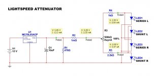
These LDRs set works with a very small current, in my circuit (see LSA_05.jpg) 5uA each at -6dB volume position, showing a resultant 20k, with a total of 40K each channel.
For me it's ok, i previously had a 50k normal pot, so it's nearly the same. If you want a total 20k, use a 250k instead.
The solution seems to be 4 resistors for 4 LED. Not a problem, isn't it? But i like it simple...
Luckily, there's a correlation between If curve and the value of the resistor of the LDR, i mean its progression, measuring with 100, 200, 300, 400k, as Uriah does.
If two LDRs are so well matched to show, for example, 0,1dB along its entire range, Led side will be almost the same.
Uriah matches them in pair, so let's use his work. We can put 2 resistors after the pot, one for each leg, no resistor before the pot, and no chaos appears.
Now look at "LSA_05.jpg", R2 is negligible, it was here to simulate the previous 1k. Situation (V and I) is identical to LSA_02.jpg of the part 1 post.
But now we have 2 resistors after the pot and the advantage is shown in LSA_04 and LSA_06.
Now the pot always sees a correct 5V in every position, even at extremes. current is too different from LSA_01 and LSA_03.
We have a minimum of about 2,5uA for each LDR, not pAs! And that 2 different values of R4 and R5?
Note that we have 2 new maximum: 1,16mA for R5 at 0% and 2,55mA for R4 at 100%.
Who listen with a full throttle volume? Most systems clip at 3 o' clock or even before, at 95% you soon have 1mA again.
Logarithmic curve is now a bit compressed at full position and a bit linearized when full down.
I can really live without a 100% volume position but not without a very low position, like background music.
It won't go totally off, depends on the gain of the entire system, with my 40Wch amp and 92dB speakers, i can only hear a whisper.
I have that old habitude to close the volume when powering off the amp, now i know that i cannot overload that 500K 1/2W pot with 1mA flowing.
For all other positions, R4 and R5 are negligible with a 500k, but if you need a 250K, you need to modify them.
Now it's really working, i replaced my old pot, so when i power off the amp, the LSA will also go off. Super safe i think.
This is possible with the matched sets showing 10K with a 400K resistor in series, as Uriah's chart reports.
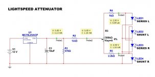
Now the "look" is just like the last image below, not too elegant, i know...
That's it, please tell me what do you think...
Thanks,
Gianni
Hi everyone,
i left with the story about the leds being not a "democratic" current devices.
They tend to have what they need, eating current and voltage to less hungry ones, even if they are the same devices with the same specs.
This happens when they are in parallel, just like the lsa. Problem is even worse with a pot that moves up and down and changes the current between its two legs.
Tipically, it's a common and right method to put one resistor for each led, so to avoid the unwanted interferences among them.
That's George's way, but he use a small resistor value to protect the leds, with LDR sets that show about 10k total impedance (100k pot).
I'm posting in this "500k pot LDR set" because i have these from Uriah like many of you and in this 2 posts i only talk about them.
What i read in many posts about LSA is the tolerance of resistor side, never read about LED tolerances.
But they have tolerances like any other device and they may be not too small. I'm talking about Vf and If.
They can have different curves of If, altering the rated Vf.
Example: I can feed with a ccs three leds showing 2,5V or 2,3V or 2,8V at 20mA. Again, with a stabilized 2,5V i can feed other three showing 10mA or 15mA, etc.
The way Uriah does his wonderfully matched LDRs is the second one, in fact they don't match anymore in a CCS supply.
If we want to appreciate his patient and great work we have to "clone" his setup: 5V -> resistor -> LDR.
The same resistors for all of them, selecting the resistance values on the other side. But this can happen with different amounts of voltage and current, depending on LDRs tolerances.
Anyway, one resistor for each LDR, how can it be the same with a splitting pot and a single resistor before the pot?
Leds will start to fight, dropping voltage here and there to the others, depending on the current they need. They are leds, not lamps.
First, the resistor will produce a consistent voltage drop if it is 1k to limit the current, then it will be a chaos after it, i measured 1,4V at extreme positions!
These LDRs set works with a very small current, in my circuit (see LSA_05.jpg) 5uA each at -6dB volume position, showing a resultant 20k, with a total of 40K each channel.
For me it's ok, i previously had a 50k normal pot, so it's nearly the same. If you want a total 20k, use a 250k instead.
The solution seems to be 4 resistors for 4 LED. Not a problem, isn't it? But i like it simple...
Luckily, there's a correlation between If curve and the value of the resistor of the LDR, i mean its progression, measuring with 100, 200, 300, 400k, as Uriah does.
If two LDRs are so well matched to show, for example, 0,1dB along its entire range, Led side will be almost the same.
Uriah matches them in pair, so let's use his work. We can put 2 resistors after the pot, one for each leg, no resistor before the pot, and no chaos appears.
Now look at "LSA_05.jpg", R2 is negligible, it was here to simulate the previous 1k. Situation (V and I) is identical to LSA_02.jpg of the part 1 post.
But now we have 2 resistors after the pot and the advantage is shown in LSA_04 and LSA_06.
Now the pot always sees a correct 5V in every position, even at extremes. current is too different from LSA_01 and LSA_03.
We have a minimum of about 2,5uA for each LDR, not pAs! And that 2 different values of R4 and R5?
Note that we have 2 new maximum: 1,16mA for R5 at 0% and 2,55mA for R4 at 100%.
Who listen with a full throttle volume? Most systems clip at 3 o' clock or even before, at 95% you soon have 1mA again.
Logarithmic curve is now a bit compressed at full position and a bit linearized when full down.
I can really live without a 100% volume position but not without a very low position, like background music.
It won't go totally off, depends on the gain of the entire system, with my 40Wch amp and 92dB speakers, i can only hear a whisper.
I have that old habitude to close the volume when powering off the amp, now i know that i cannot overload that 500K 1/2W pot with 1mA flowing.
For all other positions, R4 and R5 are negligible with a 500k, but if you need a 250K, you need to modify them.
Now it's really working, i replaced my old pot, so when i power off the amp, the LSA will also go off. Super safe i think.
This is possible with the matched sets showing 10K with a 400K resistor in series, as Uriah's chart reports.
Now the "look" is just like the last image below, not too elegant, i know...
That's it, please tell me what do you think...
Thanks,
Gianni
Attachments


My comments:
Try it, I think I will and I dont want to have to replace pots in my preamp all the time.
It should work fine and it should be a bit louder than normal at min listening position because we can not now get the shunt LDRs as bright as normal. This is fine. Dont sweat it, just try it.
Instead of resistors of that exact value following the pot it would be fun to use trimmers but do not fall below the value of his spec'd resistors if you are doing this for safety of the pot. So considering you do this and you want safety then you stay above that value and tweak the pot. WHY? Because now you can change the curve of the attenuator and you may find a curve of volume increase/decrease that you find appealing and very fine for your listening.
My only complaint about the write up is the suggestion that a 250k pot should halve the value of the LDR. Its not that linear. If you want a lower impedance on your LDR pot then you should read my datasheet I sent with the LDRs and figure out the value of pot you might use from the values at 100k,200k,300k,400k. The value at 200k is usually not half of the 400k value.
Thanks Gianni. Have you yet built it this way and has it been fun!? 🙂
I love this circuit and its simplicity allows so many people to enjoy truly exquisite clarity. I hope Gianni will keep tinkering with it and reporting if he has a want to do this and I know I will keep messing with it. Kind of never stops!
Uriah
Try it? You think i wrote all this without testing and listening? 🙂My comments:
Try it, I think I will and I dont want to have to replace pots in my preamp all the time.
I already explained in my post, have you really read it?It should work fine and it should be a bit louder than normal at min listening position because we can not now get the shunt LDRs as bright as normal. This is fine. Dont sweat it, just try it.
Right, it was to help understand the concept, not the perfect value. Again, if you read my post, you will notice that i mentioned your test setup and the same values you wrote here and that i wanted a 40/50k equivalent pot, maybe i will test a 250k, but it's not a primary need.My only complaint about the write up is the suggestion that a 250k pot should halve the value of the LDR. Its not that linear. If you want a lower impedance on your LDR pot then you should read my datasheet I sent with the LDRs and figure out the value of pot you might use from the values at 100k,200k,300k,400k. The value at 200k is usually not half of the 400k value.
Yes, i will do some more tests, then, as usual, i will listen to the music, once i reached what i was searching. I hate to work and work and never enjoy!Thanks Gianni. Have you yet built it this way and has it been fun!? 🙂
I love this circuit and its simplicity allows so many people to enjoy truly exquisite clarity. I hope Gianni will keep tinkering with it and reporting if he has a want to do this and I know I will keep messing with it. Kind of never stops!
Uriah
LSA changed all tonal balance, sometimes it seems to me i changed my amp, fantastic. No harshness, true bass, really lovely!!!
I will keep reading and posting for sure, i really like LSA story 🙂
Thanks Uriah.
Gianni
Gianni,
You misunderstood me.
I was talking to others who may be reading this thread. I suggested they try it.
Have I read your post? Am I obligated to read your post? I have read it, I appreciated it and that is what I just expressed in my last post.
Do you and I really need to bash heads? I have not enjoyed it so far especially as it has been quite one sided.
Uriah
So sorry Uriah, Misundertstood 🙁 Seemed that you was replying to me, i apologize.
Problems due to different native spoken languages...
Anyway, nobody is obliged to read and undertstand my posts, unless one wants to reply or to dissence, it's obvious. I don't want to bash heads with anyone, especially with you.
I always mentioned you in my post in a very positive and thankful way.
Even my analysis of the version of the LSA starts from your matching work, trying to replicate the setup and fully appreciate what you've done for us.
P.S.
For the reasons i previously wrote, i think that in CCS you may find some new matched sets among the mountain of LDRs remained. I'm thinking to use a lm334 too, with appropriate set. We will talk about if you want, so to keep messing with LSA! 🙂
Ciao Uriah, don't worry, it can happen...
Special regards,
Gianni
Shunt LDR get half the current of the "1k before the pot" version.It should work fine and it should be a bit louder than normal at min listening position because we can not now get the shunt LDRs as bright as normal.
Uriah
It's not so bad with that set that works with very low currents.
It's the series that remains a bit on, nearly a half respect to the -6dB position, so the resistance won't go too high.
But this also flattens at the extremes the floating input impedance that i get before.
Let me know if you will try these modifications.
Regards,
Gianni
Attachments

I don't understand why the 1k0 and 2k2 in series with the LEDs are different.
Could you explain.
Similarly, if one requires a wide range of volume (SPL) adjustment then the shunt LDR must go to low resistance. This requires it's LED to be fed with high current and this demands that the series resistors must be low in value.
Why adopt 2k2 as the series resistor? 200r would allow a much lower LDR value and protect the LED from over current?
I see a pair of parallel LEDs fed from a single 2k2 or single 1k0. Could you update the drawing to show the 4 resistors?
Why do LEDs with 5uA and 1.1mA passing show the same Vf of 2.50Vdc? Same for 2.5mA and 250pA?
Last edited:
Andrew, i know it's a bit too long post, but i think i already explained there at 95% of your questions.
Except for the last: Multisim 10 have its limitations, especially with virtual devices like the leds. I don't have modellized ones in the database. It's correct for the current, not with the voltage. In this case it is uninfluent, i was pointing out about current sharings, explaining why 2 resistors, why they are different and why they are only apparently high values, instead perfectly working with the "500k pot LDRs set".
Regards,
Gianni
- Status
- Not open for further replies.
- Home
- Group Buys
- Silonex LDRs for Lightspeed Attenuator