Hi Andrew,
Just curious, how do you derive these numbers such as <= 1ma for a 500K 500 mw pot? When pot is fully open, the 5V is shorted to one pin, the other pin (with full 500K) will get uA flow through at best.
In my case (one single gang 200K pot per channel, each ldr is in series with a 485R resistor, and the output of the 7805 is connected to the wiper directly). When the pot is full attenuated, the shunt ldr draws 6.7ma, and the series ldr draws approx 1ua. Since the pin that draws the heaviest current is shorted to the wiper, this shouldn't cause any harm to the pot, right? In other words, the 3ma (or so) max current through the pot doesn't apply in this position.
Another interesting observation is that, as soon as the pot is turned, the current drawn on the series side actually decreases until 9 o'clock, where the current drawn by the shunt decreases rather rapidly and gone below 1ma at around 9 o'clock. I tried a few different pots. They all exhibited this phenomenon. I also found that the most linear position is typical between 10 to 2 o'clock. When in this range, both ldr's draw way less than 1ma.
Notice I used 485R in series with each ldr per channel, if the pot is used for both channels, and one resistor is used in between the 5V and the wiper. I can simply use a 240R resistor to get the same result for the same set of ldr's. Based on similar measurements from a few sets of LDR's, I think this is enough to protect the ldr's as well as the pot as long as the pot is always set at 9-3.
FWIW, my LDR's are also the same gentleman Uriah. I just happened want to learn this beast and gone through different matching methods.
Cheers,
I just tested this method. It is NO GOOD. Inserting a resistor in between the 5V and the wiper turned out to be not a good idea. The problem with this method is that the range of linear (or consistent impedance) is very narrow. For the sake of validating my statement above, I first tested one pot/2 channels with 485R in series of all 4 ldr's. Then I bypass all the 485R and inserted 1 x 240R in between wiper and 5V. The very first different caught my eye was exactly what Gianni saw, the series ldr's were all in 4meg ohm range when the pot is a fully attenuated pos. In my original MK II like build, these ldr's were at around 60K. Then I turned up the pot, the series ldr's didn't the same resistance until the pot passed 10 o'clock.Notice I used 485R in series with each ldr per channel, if the pot is used for both channels, and one resistor is used in between the 5V and the wiper. I can simply use a 240R resistor to get the same result for the same set of ldr's. Based on similar measurements from a few sets of LDR's, I think this is enough to protect the ldr's as well as the pot as long as the pot is always set at 9-3.
I lowered the resistor to 150R, no dice either. I thought hard and came up with a theory. Notice that the voltage drop across this resistor affects both pins. When one pin draw sufficient current, the wiper's voltage will be lower which in turn limit the available available to the other pin. In my case, each shunt ldr of the 2 channels draw 6.5ma, a total of 13ma passed through the 240R which dropped 3.15 and left only 1.85V at the wiper. From my measurement, the ldr's LED consumes at least 1.35V which implied 0.5V across 200K. Obviously, there wasn't much current passing through the series ldr's!! This situation wouldn't change until the current drawn from both pins are "reasonably" close. Unfortunately, this "reasonably close" range is very narrow.
In summary, up the 100R's (200R-300R) to protect both the pot and the ldr's.
potentiometer Power rating
the maximum power rating for a variable resistor and a potentiometer is given for the WHOLE track length.
This can be used to determine the maximum current rating for the WHOLE track length and also for any part of the track.
1mA through a 500k pot is 0.001*0.001*500000=0.5W=500mW.
The track is rated for a maximum power of 500mW AND rated for a maximum current of 1mA.
I prefer to run a pot at a maximum of half power rating (<=70% of max current rating), but that's just me.
If you want to use a pot that may have to pass 20mA then a 50k pot rated at 20W will reliably survive this duty in the longer term. But the wiper may become noisy quite early in it's life. The wiper contact is not rated to pass the full track current. Anatech has a strong view on this, in part brought about by his vast experience in servicing faulty/worn out electronics equipment.
A 1k pot @ 22mA requires a 500mW rating and this is the maximum variable 1/2watt resistor value that can be used in the LED circuit, but, as we know that will NOT give us the adjustment range we need.
We must accept that the track and wiper will be run at massively over the manufacturers current/power rating at some attenuation levels. In the very wide mid range region, the current passing the track and wiper will be much less than 1mA and the pot will operate reliably for most users.
We need just 3000r or so in series with the LEDs to reduce the current to <=1mA through the wiper and track. This covers the vast majority of the travel of a 500k pot. No worries. It's only at the ends of the travel that over current becomes a longer term concern.
But that pot reliability is completely different from the LED reliability and abuse.
Here we must ensure that the LEDs never get overloaded with excess current. That's why we need a series resistor for each LED. The total series resistance needs to limit the LED current and values around 100r can do that depending on where they are fitted and how many we fit.
I don't care whether that upsets the ideal attenuation characteristic of the LED/LDR combination. Much more important to me is that these relatively expensive (to match) LEDs are not needlessly ruined by an inadvertent adjustment of a pot that does not have LED current protection.
Cool, I thought the same thing. For the pot, it will never be the case that there will be anything near 1ma or 0.5ma passing through the entire track. I don't concern this scenario; however, I also read Anatech's concern about the wiper contact, that's totally valid. Unfortunately, putting a large resistor before the wiper simply won't work, in the sense to build a function LS.
From what I tested and measured, the one resistor approach will serve the function to protect the pot and the LDR's but will not a make useful volume control. The right approach is to use one resistor on each LDR's LED. My suggestion was based on some tests I did some time ago. Since I had around 10+ unmatched LDR's, I decided to use them to explore the minimum resistance to provide fool proof protection because I wanted my match sets to last. The test was very simply, 5V -> 1 resistor -> LDR's LED. I measured the voltage across the resistor to calculate the current drawn by the LDR's LED and the voltage across it. 2 things can't be exceeded - 2.5V and 25ma.
I found 100R was NOT good enough to ensure not to exceed the max specs. At least half of those, the current never exceed 20ma, bu then the voltage was a good 3V across the LDR!!! I found 250R was quite suitable. This value will limit max to approx 11ma/1.9V when 5V is applied directly. If this value is good enough to protect one LDR, half of the resistance will be good for 2 (the resistor at the wiper case for 2 channels). I also found out that the LDR's LED draws << 1ma in the operating positions. Therefore, increasing the resistance can be used to extend the protection to the pot. However, the exact value must be determined on a case by case basis. To me, it must be 250R and above.
Andrew already calculated the max current should be <= 1ma for the 500K pot. I wanted to point out that if the pot is used by 2 channels, then each side can draw no more than 0.5ma in the extreme case. This implies a 5K resistor for full pot protection. If you are a risk taker, use less. As long as there is at least 250R, the LDR will be protected well. Only the pot can be at risk. I also want to point out an advise from George to keep the pot at the mid point to ensure long term reliability when not in use. The reason is that this is the position drawing the least current. In short, avoid too close to the extremes of the pot.
Great! Fred, we have the same bad result, so i'm not mad alone 😉
Simple resistor before the wiper doesn't work or it works on Uriah circuit only! 🙂
Higher the pot, higher the problem with the dissipation, LDRs draw all about the same current. So, matched set working with a 500k is quite unuseful and i have 2 sets!!!
Perfect, i'm very happy. If i use the 220r on each ldr they will be safe but the pot will die more frequently than that normally used as audio attenuator. If i use a resistor before the pot, it will last "forever" but the LSA won't work or it will work bad (except for Uriah and maybe others).
I soldered everything on a perfboard, even tied ldrs pin to other components to stay compact, sure that the schematic would work at the first try, blindly trusting in so many posts about this version of LSA. I NEVER do things like that and now i have to learn once more that i was doing well before this experience...good.
With a heavy bending and soldering on LDRs, it will be a real problem to take them out, but it's my fault.
George, with his experience on LSA, did a 2 gang pot design and 4 resistors, ok, still having problem if you frequently leave the volume full off or on, but there will be a good reason for that schematic, i'm sure...
Real problem is that there's no good solution to have a long lasting AND working LSA, especially with the set that need a 500k pot, which is the most part of the problem.
To have a 200/70/200k log attenuator is not my kind of volume, it sounds, yes, but very, how can i say, soft, slow, muddy, with this high and unstable impedance.
After this little outburst, mostly with myself, i have to think something, i'm a diyer since i was 10, never stopped to learn and study electronics, built and originally designed lots of audio equipments for me and many others using tubes, bjts, fets (i love them) and op-amps that i refuse the idea that i cannot found a REAL solution, grrrr! And i want to use THIS matched set.
Thanks to Uriah, Fred and Andrews and all the others for their great help and ideas.
Ad maiora,
Gianni
Last edited:
Hi Gianni,
Don't let me to discourage you. How often the pot will die is still unknown. As long as you remember not to leave the pot at the extreme position for too long, I think the pot will last longer than your fear. I hope there is enough room for you to solder, let say, some 470R to each LDR.
To be honest with you, I thought the single resistor would work, but I never tried until yesterday. I experienced similar result as yours with totally different LDR"s and pots which seemed to indicate George's original MK II design is the way to go, and that's what I use from the beginning.
I also suspect the single gang pot may not work as well as the dual gang because of some odd behavior that I said in previous post. Both the single gang and dual gang approaches provide the "see-saw" effect of the series and shunt, but the dual gang provides separate tracks for the series and the shunt. This simply isolates the series and the shunt from seeing each other's change. Need to go to Radio Shack to pick a couple dual gang pots to try out......
The RS pot's rating was too low. I had to rob a dual gang 100K pot from one of my tube amps to test it out. The dual gang DID FIX the odd behavior (the series LDR's resistance would go up as the pot started to turn from full attenuate position until 9-10 o'clock). My LS now stays at the 25K +/- 7% range through out 90% of the position, and there was no bump at the beginning.
Time to buy a few more dual gang pots of different values .......
Time to buy a few more dual gang pots of different values .......
So Fred, you think this is completely to do with 1k in series? Its seems you have done the tests to prove it. I never tested, it just worked so I didnt bother with measuring. The math worked and the whole thing sounded great. I have it on loan to my friend in Austin right now. I get it back in October. If thats the case I wont recommend 1k any longer.
Its just odd to me that 1k, that is in series with on average 250k makes any difference since it would be seen, should be anyway, as one single resistor.
Thanks for sorting it out, I sincerely appreciate it.
Uriah
Its just odd to me that 1k, that is in series with on average 250k makes any difference since it would be seen, should be anyway, as one single resistor.
Thanks for sorting it out, I sincerely appreciate it.
Uriah
I am now thinking about dual gang again but to put 5V in the back of the gang that controls series and in the front of the gang that controls shunt then out the wiper instead of in the wipers and out the sides. In the wipers seems like something that could damage pots over time because the wiper is made to carry small currents that have already been though resistance.
Ultimately I would like to get rid of pots and use LM334 but this is a half year or so away and will take a lot of testing.
Uriah
Ultimately I would like to get rid of pots and use LM334 but this is a half year or so away and will take a lot of testing.
Uriah
Hi Uriah,
I didn't mean to say that the single resistor approach would't work as my tests were upon a couple different pots and a couple sets of matched LDR's of different sensitivities. I think the resulting impedance of the LS pot are high in the extreme positions maybe the normal with this approach, but the "side effect" of this is only a narrow "normal" range. If the normal listening loudness happens to be within this range, there shouldn't be any different SQ than the "classic MK II" approach, IMHO.
I also found that the value of this single resistor, the value of pot, and the sensitivity of the LDR's would vary the size of this range. However, I failed to figure out the rule of thumb of the values of the component to use. I think converting to use a dual gang pot will also help.
Move the resistors to the "OUT" pins of the shunt and the series effectively give the same result as the original MK II design at a saving of 2 less resistors. So, it will work just as good. The crucial part is the dual gang pot.
Right now, all I am doing is voltage based. I would also like to try the CCS version. Of course, this also means that I have to redo the matching based on the CCS circuit, not something I am looking for in the near future 🙂
BTW, when you get your toy back from your friend. Take some measurement to see you get similar result.
Its a guarantee. I really want to see whats going on. I used a mini trimmer so I will be able to see pretty quick whats up with that series resistor and the odd results.
Uriah
Uriah
My LDR's are much less sensitive than your previous batch.
When I ran those tests as in previous post, I used the most sensitive and the least sensitive sets. The interesting part of watching the voltage of the legs was that I could tell how far the LDR's were from the "operating range". It is a good visual to see the electrical properties vary vs the output resistance as the pot is turned.
When I ran those tests as in previous post, I used the most sensitive and the least sensitive sets. The interesting part of watching the voltage of the legs was that I could tell how far the LDR's were from the "operating range". It is a good visual to see the electrical properties vary vs the output resistance as the pot is turned.
Found an explanation and possible solutions (part 1)
Hi there,
as promised before, i never give up. Thought and thought starting from the beginning and that's what i found and did. Explanations are for everybody, so expert diyers don't laugh!
Fred is on the right way with his empirical approach and i thank him for getting to the same result i had, this was the kick i needed. 🙂
I'll try to be clear, nevertheless my english...
The idea to put a 1k or any other value of the resistor, BEFORE the single pot and with no single R for each LDR, is a complete failure, starting from the concept that it protects both the pot and LDRs.
Why before? It's the load that sets the current value required, not the contrary.
In that position, one may say that 1k vs. 500k is negligible. But when i move to the beginning or end of a LOG pot, i have very small values in series with 1k, so it's influence is not so negligible and it reacts dinamically with the pot.
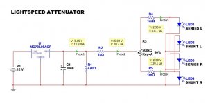
Since it works as a current limiter, it will have a voltage drop across it, with the worst cases at the extreme positions. In fact, in the middle, from 11 to 2 o' clock, LSA works well, the current is at minimum and 1k don't drop significant voltage. (LSA_02.jpg)
When series or shunt ldr resistors start to draw more current, the 1k begin to drop too much voltage and referring to LSA_01 and LSA_03 i have a 2,5V drop before the pot to limit the current to 2,5mA. Two problems: First, the current is still too high for a 500k 1/2W pot as Andrew said several times (max 1mA to stay in the rating). Second, the "low" arms of the pot show values of pA, so the LDRs are nearly off and give to their resistor an incredible high value, over 4Mohm. This explains the "toothsaw" impedance, going from 200k to 50k and to 200k again at 0dB (full up) and the deriving high overall value, in general. We cannot hang all the circuit to a single resistor, as it interferes interactively with everything that follows.
Led are current devices and don't like to share their current with too many components around with different consumptions. George in fact, designed its LSA with a resistor for each LDR (and a dual gang pot to limit power rating problems) and nothing before the pot. However, those R100s protect the leds only, but not enough the pot.
I found a workaround or possible solution if you prefer, that solves and transforms the problem with these matched sets that requires a delicate 250/500k in one of the best LSA.
It's simpler than George MKII, cheap as Uriah schematic, safe for the pots and perfectly working! Time finished, to be continued...
Hi there,
as promised before, i never give up. Thought and thought starting from the beginning and that's what i found and did. Explanations are for everybody, so expert diyers don't laugh!
Fred is on the right way with his empirical approach and i thank him for getting to the same result i had, this was the kick i needed. 🙂
I'll try to be clear, nevertheless my english...
The idea to put a 1k or any other value of the resistor, BEFORE the single pot and with no single R for each LDR, is a complete failure, starting from the concept that it protects both the pot and LDRs.
Why before? It's the load that sets the current value required, not the contrary.
In that position, one may say that 1k vs. 500k is negligible. But when i move to the beginning or end of a LOG pot, i have very small values in series with 1k, so it's influence is not so negligible and it reacts dinamically with the pot.
Since it works as a current limiter, it will have a voltage drop across it, with the worst cases at the extreme positions. In fact, in the middle, from 11 to 2 o' clock, LSA works well, the current is at minimum and 1k don't drop significant voltage. (LSA_02.jpg)
When series or shunt ldr resistors start to draw more current, the 1k begin to drop too much voltage and referring to LSA_01 and LSA_03 i have a 2,5V drop before the pot to limit the current to 2,5mA. Two problems: First, the current is still too high for a 500k 1/2W pot as Andrew said several times (max 1mA to stay in the rating). Second, the "low" arms of the pot show values of pA, so the LDRs are nearly off and give to their resistor an incredible high value, over 4Mohm. This explains the "toothsaw" impedance, going from 200k to 50k and to 200k again at 0dB (full up) and the deriving high overall value, in general. We cannot hang all the circuit to a single resistor, as it interferes interactively with everything that follows.
Led are current devices and don't like to share their current with too many components around with different consumptions. George in fact, designed its LSA with a resistor for each LDR (and a dual gang pot to limit power rating problems) and nothing before the pot. However, those R100s protect the leds only, but not enough the pot.
I found a workaround or possible solution if you prefer, that solves and transforms the problem with these matched sets that requires a delicate 250/500k in one of the best LSA.
It's simpler than George MKII, cheap as Uriah schematic, safe for the pots and perfectly working! Time finished, to be continued...
Attachments

100R feed resistor is equivalent to 200R in between feed and LDR's LED. It should serve the function to protect the LDR's. I will give it a try when I get home tonight. However, given I had seen LDR's that drawn quite a bit lower than the 25ma max per specs, I wouldn't go lower than 100R for the LDR's longevity unless I can measure the characteristics of the LDR's. Overvoltage can be bad, too.
- Status
- Not open for further replies.
- Home
- Group Buys
- Silonex LDRs for Lightspeed Attenuator