right yep i see how that works now with the current control through the RX resistorQ410 is the multiplier. The voltage between C and E will determine when and how hard the driver and output transistors conduct.
You could think of Q410 as being just a variable resistor between the driver transistor bases but the main reason we use a transistor to do the job is because it allows us to thermally compensate the output stage so that the current remains constant with temperature change. Those you have circled are the drivers.
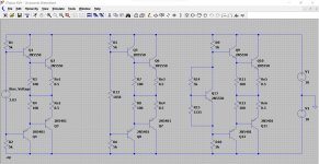
ah ha, now i see why that transistor is mounted on the heatsink
 it can then track the temperature of the output stage.
yes i can see why it is so important now to control the idle current at that point, as it would run away if the value of RX was too low allowing too much current to flow to the base of Q410?
and R 454 splits the current, is this to aid control at that point?
and R 454 splits the current, is this to aid control at that point?
Last edited:
R452 and R454 are a simple voltage divider (like a volume control) that allows the conduction point of the transistor to be precisely set.
Look at this DC simulation. It is the output stage in three different setups. On the left is a theoretical voltage source of 3.03 which by trial and error (no other way to do it) is found to give 50 milliamps bias current.
The middle version simply uses a fixed resistor to develop that voltage. Lets see if it can be calculated. We know the base current into the drivers will be very tiny so lets ignore that and go for a simple ohms law calculation.
20 volts total supply and three series resistors, 5k +5k + ? (unknown)
We know we need 3.03 volts and so that leave 20 - 3.03 to be dropped across the two 5k's which is 16.97 volts
So that reduces to a single 10k in series with the unknown value we want. The 10k has to drop 16.97 volts and so the current is 16.97/10000 which is 0.001697 or 1.697 milliamps.
So our unknown value must be R=V/I which is 3.03/0.001697 which is 1785 ohms.
That puts us in the right ballpark. The value that was needed turned out to be 1858 ohms. Why the error. Because the tiny base current (an unknown) and the corresponding B - E volt drops are modifying or pulling our wanted voltage away from where it should be.
The vbe multiplier can use any sensible values of resistor for setting the base current of the transistor. They just need to be low enough to ensure that transistor variations in gain from one part to another are swamped out.
The vbe multiplier also helps keep the generated bias voltage more constant with changes in current through the multiplier that might occur if the supply voltages change a little for example. And you have the temperature compensation.
As the output stage warms it tends to conduct more. Transistor gain increases with temperature and vbe falls so the transistors conduct more for the same fixed bias voltage.
If you make the multiplier change temperature as well then its voltage across C and E also falls as it heats up and this is automatically pulls the output stage bias point back down.
The resistor R450 is a refinement that further helps match the multiplier to the output stage to ensure even better tracking with temperature.
Attachments
Im having to read this a few times so i fully understand
i've been reading about amplifier's that have a 'push-pull' effect
Is this what you are referring to the voltage being 'pulled away'
and presumably then if the heatsink was in sufficient it would run away as the amp was driven harder?
do/can individual components add to distortion in any way?
i've been reading about amplifier's that have a 'push-pull' effect
Is this what you are referring to the voltage being 'pulled away'
and presumably then if the heatsink was in sufficient it would run away as the amp was driven harder?
do/can individual components add to distortion in any way?
R452 and R454 are a simple voltage divider (like a volume control) that allows the conduction point of the transistor to be precisely set.
Look at this DC simulation. It is the output stage in three different setups. On the left is a theoretical voltage source of 3.03 which by trial and error (no other way to do it) is found to give 50 milliamps bias current.
The middle version simply uses a fixed resistor to develop that voltage. Lets see if it can be calculated. We know the base current into the drivers will be very tiny so lets ignore that and go for a simple ohms law calculation.
20 volts total supply and three series resistors, 5k +5k + ? (unknown)
We know we need 3.03 volts and so that leave 20 - 3.03 to be dropped across the two 5k's which is 16.97 volts
So that reduces to a single 10k in series with the unknown value we want. The 10k has to drop 16.97 volts and so the current is 16.97/10000 which is 0.001697 or 1.697 milliamps.
So our unknown value must be R=V/I which is 3.03/0.001697 which is 1785 ohms.
That puts us in the right ballpark. The value that was needed turned out to be 1858 ohms. Why the error. Because the tiny base current (an unknown) and the corresponding B - E volt drops are modifying or pulling our wanted voltage away from where it should be.
The vbe multiplier can use any sensible values of resistor for setting the base current of the transistor. They just need to be low enough to ensure that transistor variations in gain from one part to another are swamped out.
The vbe multiplier also helps keep the generated bias voltage more constant with changes in current through the multiplier that might occur if the supply voltages change a little for example. And you have the temperature compensation.
As the output stage warms it tends to conduct more. Transistor gain increases with temperature and vbe falls so the transistors conduct more for the same fixed bias voltage.
If you make the multiplier change temperature as well then its voltage across C and E also falls as it heats up and this is automatically pulls the output stage bias point back down.
The resistor R450 is a refinement that further helps match the multiplier to the output stage to ensure even better tracking with temperature.
'Transistor gain increases with temperature and vbe falls so the transistors conduct more for the same fixed bias voltage'-
why does the vbe gain fall as it heats up?
Push pull refers to output stages like you have been used to where there is an upper and lower half (usually with an NPN and a PNP transistor) and that run with minimal bias current. The upper half can 'push' current into the load and the lower half can 'pull' the current through the load. The efficiency is high and that is one reason it is commonly used.
Push–pull output - Wikipedia
I meant pushing or pulling the voltage away from its target value by the loading of the driver stages 🙂
Transistor gain and vbe variation with temperature are actual physical properties of silicon transistors determined by the actual material properties.
vbe varies by -2.2mv per degree centigrade so if you fixed the bias voltage at some level then as the transistors heated then vbe would reduce by that amount per degree C
As vbe is reduced, the base current provided by the fixed bias voltage source (the current flowing into the base of the transistor) would therefore increase and so overall the bias current increases. Then it gets hotter still and more current flows and so on.
Using the vbe multiplier means that as that particular transistor heats and turns on more, its voltage across C and E will fall and it is that C-E voltage that is our bias setting voltage. So more heat in the output stage means less bias voltage available and so it becomes self regulating and pretty constant.
If the transistor was not touching the heatsink then the effect of reducing bias with temperature would be largely lost.
so given manufacturing of components can vary in quality, a 2N3055 or a 2sd699a might also vary in how it performs?
so you couldn't assume by replacing a part that it will perform exactly the same as the previous part?
so you couldn't assume by replacing a part that it will perform exactly the same as the previous part?
Parts from the same manufacturing run or batch should match pretty closely but even then there are still small differences.
Something like a 2N3055 is historically a really old device and you will find modern 2N3055's are quite different in their specifications although they should still work OK as replacements in older equipment. Manufacturing processes change and improve over time.
2N3055 - Wikipedia
The differences often don't matter as much as you might think (as a generalisation) because a complete circuit such as an amplifier is designed to work over a wide range of values. For example if the gain range of the transistors (the hFE) is quoted as between 40 and 250 and the cutoff frequency is 40 to 70Mhz then the amplifier will perform the same if worst case or best case specification parts are used.
Negative feedback is what makes that possible.
do you think i could have overloaded and fried either of the 2 circled, ive not looked yet but thought these were the possibly the victimsOh dear 🙁 although if you short the multiplier out to get zero bias then there is no need to actually touch the bias preset. To put a bit of positive spin on it though, that kind of event is something that we all have done and we all learn from it.
Your good on NAD's, I've no doubt it will be up and running in no time 🙂
The site is looking good but it is going to be a steep learning curve in one or two areas.
The 3.3 ohm across the coil should be immune to any failure. The low resistance coil protects it and in any case even if the resistor were open you would notice no difference with the amp. Its function is to damp ringing caused by the coil in combination with capacitive loading. No resistor and you see ringing on squarewave testing.
The 10 ohm can fry if the amp is delivering really high frequency test signals at very high volume. That is a critical part but can easily be checked in circuit. The series caps ensure you get a true reading without having to isolate it.
Interesting about the caps in series, i didn't know that so that's something else I've learned today 🙂The site is looking good but it is going to be a steep learning curve in one or two areas.
The 3.3 ohm across the coil should be immune to any failure. The low resistance coil protects it and in any case even if the resistor were open you would notice no difference with the amp. Its function is to damp ringing caused by the coil in combination with capacitive loading. No resistor and you see ringing on squarewave testing.
The 10 ohm can fry if the amp is delivering really high frequency test signals at very high volume. That is a critical part but can easily be checked in circuit. The series caps ensure you get a true reading without having to isolate it.
well something in that direction defiantly went 'fizzing' ,although there is no visible sign of failure or burning so its back to the bench 🙂
Last edited:
The caps block DC and so the meter gets a true reading of the resistor. If there were other parts across the resistor such as diodes/transistors etc then that would not be the case. Also the caps are low value and so the meter used on its ohms range will almost instantly charge them to the meters test voltage and once that happens they have no effect on the reading. If the caps happened to be big electrolytics then that would not apply because the cap would take a long time to charge and also leakage current in the cap could become a factor and alter the result.
As a general rule the lower the value of a resistor and the better chance you have of testing it in circuit accurately.
As a general rule the lower the value of a resistor and the better chance you have of testing it in circuit accurately.
so would this apply to any low value cap that was in series with a resistor? or would you still lift a leg to check?The caps block DC and so the meter gets a true reading of the resistor. If there were other parts across the resistor such as diodes/transistors etc then that would not be the case. Also the caps are low value and so the meter used on its ohms range will almost instantly charge them to the meters test voltage and once that happens they have no effect on the reading. If the caps happened to be big electrolytics then that would not apply because the cap would take a long time to charge and also leakage current in the cap could become a factor and alter the result.
As a general rule the lower the value of a resistor and the better chance you have of testing it in circuit accurately.
As you get experienced you will start to know when you can trust the result. If the measured resistor value is lower than expected then its most likely that something is effecting the result. If it is higher then it could be that either the resistor is genuinely faulty or that some residual voltage in the circuit (it only needs a few tens of millivolts) could be confusing the DVM.
So generally if a resistor measures correctly in circuit it more than likely is OK, if it doesn't then you have to isolate it and prove it good or otherwise.
Another tell tale is getting different resistance readings depending which way around you connect the probes. It shoul make no difference. If it does then something is interfering with the result.
- Home
- Design & Build
- Equipment & Tools
- Siglent SDS1202X-E New to use of equipment.