because the eventual aim is to have a 0 volt centre? and distortion we are refering to isnt audible is it?Think theory 🙂
You normally have a driver transistor and an output in each upper and lower part of the output stage.
You know how much voltage you need to turn on a transistor (0.6v across base and emitter) and so you have four base/emitter volt drops to overcome. So there is a dead zone or dead band of 1.2 volts (for each upper and lower half of the stage) where the output devices don't conduct. That missing part is crossover distortion.
So why does it not look all that bad in a real amp if I just said you have a missing dead zone of -/+ 1.2 volts?
Answers on a postcard 😉
Well crossover distortion is massively audible. If you can try it on an amp and see the distortion on the scope then you will hear it. It is very distinctive when you listen to a pure sine.
The reason it doesn't look so bad in a real amp is because the output stage is wrapped up in the main global feedback loop and when that dead zone is reached then the stages before the driver make a sudden jump to try and counter the error.
I'll try and show it on a sim.
The reason it doesn't look so bad in a real amp is because the output stage is wrapped up in the main global feedback loop and when that dead zone is reached then the stages before the driver make a sudden jump to try and counter the error.
I'll try and show it on a sim.
Well crossover distortion is massively audible. ...I'll try and show it on a sim.
Attachments
Thanks muchly PRR 🙂
Here we go...
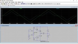
This shows a triangular wave. Look at the input voltage vs time (just like your scope will show). With no bias voltage the transistors can not conduct until the input voltage has risen (or fallen) enough to turn on either the upper or lower pair of transistors.
When we add a bias voltage we bring the transistors up to the point of conduction so that there is no 'dead zone'.
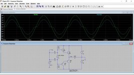
The last image is on a sine wave with no bias. Have a play with adjusting the the bias voltage in the sim.
You will see it is critical and that a tiny increase above the point where the transistors begin to conduct will cause a massive current to flow.
You will also find that a very small bias current effectively stops the distortion.
Here we go...
This shows a triangular wave. Look at the input voltage vs time (just like your scope will show). With no bias voltage the transistors can not conduct until the input voltage has risen (or fallen) enough to turn on either the upper or lower pair of transistors.
When we add a bias voltage we bring the transistors up to the point of conduction so that there is no 'dead zone'.
The last image is on a sine wave with no bias. Have a play with adjusting the the bias voltage in the sim.
You will see it is critical and that a tiny increase above the point where the transistors begin to conduct will cause a massive current to flow.
You will also find that a very small bias current effectively stops the distortion.
Attachments

ok so i get it now, or pretty much.
in the sim the distortion starts to dissapear after around 3v is applied as the bias
this over comes the shortfall that is lost with the transistor volt drops?
in the sim the distortion starts to dissapear after around 3v is applied as the bias
this over comes the shortfall that is lost with the transistor volt drops?
That's right, the 3 volts is needed to just bring the output stage to the point of conduction. In a circuit like the sim the actual voltage needed is super critical and depends on the models used.
In a real world build it is actually just as critical but again the actual voltage will be different for all different transistor types.
You might like this 🙂
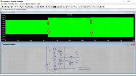
The simulation has been set to run for 30 seconds and the bias current is set at zero for the first ten seconds, then it increases to 0.6milliamps from ten seconds to twenty second and finally increases again from twenty to thirty seconds.
You can see that bias change in the first image. The sim is showing the emitter current of one of the output transistors.
We now do a neat trick... we can record the sine wave into an audio file 🙂 and that is posted here in the zipped folder. It is just an MP3 file that plays for 30 seconds and you can hear the change in the 'tone' as the crossover distortion becomes less and less.
So you can have a listen 😉
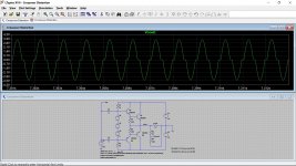
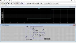
The second image shows the audio output and the bias changeover points.
The third, fourth and fifth images show what the audio looks like (as on a scope) at each bias value.
In a real world build it is actually just as critical but again the actual voltage will be different for all different transistor types.
You might like this 🙂
The simulation has been set to run for 30 seconds and the bias current is set at zero for the first ten seconds, then it increases to 0.6milliamps from ten seconds to twenty second and finally increases again from twenty to thirty seconds.
You can see that bias change in the first image. The sim is showing the emitter current of one of the output transistors.
We now do a neat trick... we can record the sine wave into an audio file 🙂 and that is posted here in the zipped folder. It is just an MP3 file that plays for 30 seconds and you can hear the change in the 'tone' as the crossover distortion becomes less and less.
So you can have a listen 😉
The second image shows the audio output and the bias changeover points.
The third, fourth and fifth images show what the audio looks like (as on a scope) at each bias value.
Attachments


pls remove that button from the front panel😀Push the "auto setup" (or similar name) button.
I would suggest if you try it to just link out the vbe multiplier on one channel of the amp. That will force zero bias without you having to alter anything.
Test the amp at say 1 volt peak to peak output voltage (as low as that) into 4 or 8 ohms. Use a sine wave of between 1kHz and 10kHz.
It should look a bit like this which is a sim of the Europa amp at 10kHz and 1kHz. The distortion occurs at the 'zero' crossing point of the signal.
Oh dear i think i wet to far with the idle adjustment 🙁 and something just fried at the back of the amp 😱, so what was..............lol a perfectly good working order unit, that ive only just finished repairing, is toast for the moment !!
Oh dear 🙁 although if you short the multiplier out to get zero bias then there is no need to actually touch the bias preset. To put a bit of positive spin on it though, that kind of event is something that we all have done and we all learn from it.
Your good on NAD's, I've no doubt it will be up and running in no time 🙂
Your good on NAD's, I've no doubt it will be up and running in no time 🙂
lol ,well not today, but ill get it fixed, it looked like ti came from near the output part of the board, i mgith have overloaded it like you suggested in an earlier part of the thread.
at least the scope is ok, and i did, very briefly see the distortion on the scope.
Ive been trying to get my head round the thevenin therory, wow thats heavy stuff isnt it, and im not sure i realy need this, but ill read it anyway.
at least the scope is ok, and i did, very briefly see the distortion on the scope.
Ive been trying to get my head round the thevenin therory, wow thats heavy stuff isnt it, and im not sure i realy need this, but ill read it anyway.
You won't use Thevenin for this kind of work but it is useful to have an idea of what it is all about.
It only applies to networks of passive linear parts like resistors and caps and tbh its something I've never thought much about since leaving college.
You'll find lots of worked examples on the web to help you understand what its about and how to reduce a network down to a simple voltage source and series resistance that will behave the same as each other to the load of interest
Try it in LTspice if you are interested using a really simple network and load and then reduce that down to a single voltage source and series resistor so that both the network and the Thevenin equivalent behave the same as you vary the load. One for a rainy day...
You won't use it for fixing your NAD though 😉
Im reading paul horowitz The art of electronics from the start and its the subject im currently reading.
If im being hounest with myself its proberbly more suited to a guy whos doing uni, but if i learn things along the way then, all the better.
there are subjects i will be reading with more intent TBH, but its all interesting reading, if a little over my head.😱
Im also reading books by charles platt, encyclopia of electronics, and they are a bit more gentle of this old brain of mine lol
Theory is essential but it has to go along with practice as well. I used to love reading books like those. Constantly getting them from libraries and so because it was all before the internet of course.
That is true, there is so much out there now on the net.
Im doing 2 courses on line as well, in my own time as i have no need to rush anything
They are both udemy courses
al's electronic class room-albert spinosa and
crash course in electronics and PBC design-Andre LaMothe
not sure if these guys are known well in the field or not, but they seem ok.
thing is fitting it all in.
approaching 59 years i guess its quite a brave thing to do and im finding work these days gets in the way, and its a real balancing act!!!🙂
Not enough hours in the day... I know that feeling.
I always enjoyed the practical side of it, building things and figuring it all out, lots of magic smoke at times but you learn. Two years full time at college doing electronics and radio and tv.
Nothing beats making something like an amplifier and connecting it up and hearing it actually work for the first time.
I've not heard of those courses but they look useful and interesting, great that you are doing something like that.
Oh dear 🙁 although if you short the multiplier out to get zero bias then there is no need to actually touch the bias preset. To put a bit of positive spin on it though, that kind of event is something that we all have done and we all learn from it.
Your good on NAD's, I've no doubt it will be up and running in no time 🙂
so in this amp, is this the multiplier?
Attachments
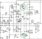
Q410 is the multiplier. The voltage between C and E will determine when and how hard the driver and output transistors conduct.
You could think of Q410 as being just a variable resistor between the driver transistor bases but the main reason we use a transistor to do the job is because it allows us to thermally compensate the output stage so that the current remains constant with temperature change. Those you have circled are the drivers.
You could think of Q410 as being just a variable resistor between the driver transistor bases but the main reason we use a transistor to do the job is because it allows us to thermally compensate the output stage so that the current remains constant with temperature change. Those you have circled are the drivers.
- Home
- Design & Build
- Equipment & Tools
- Siglent SDS1202X-E New to use of equipment.