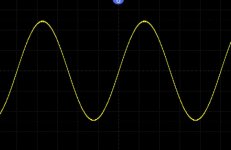
'Now increase the level of the generator to give say 6 volts peak to peak (so six squares of amplitude from top to bottom of the sine)'
how am i assertaining the voltage from the generator as i assumed it was frequency only
You have the ability to set both frequency and level on the generator... and that is one reason for having a scope 😉 to accurately measure signal amplitudes.
If I had a digital scope I could tell you what to do, but I haven't. On analogue I would select 1 volt/division for the vertical scale and then increase the amplitude to give six squares of deflection (top to bottom) if I were using a X1 probe or simple lead. With a X10 probe (a divider probe) I would set the scope to 0.1volts /division
You should try and get in the habit of using the scope manually rather than relying on the auto feature as it will help you get a feel for levels and such like.
This image is from your scope manual and if this were set to 1 volt per division the amplitude here would be 5 volts peak to peak.
Attachments
i see what you mean.i havent got the hang of it properly yet, and it could take some time as some of the terminology is alien still to me.
so i get the scaling, each sq (up/voltage) x1= what ever scale you set it at
so if you set it at 500mv each incriment is 500mv right? and the horitontal is time?
what im dissapointed at with this is that ,a simple reading over a battery, pure dc is a straight line, i get that, but it doesnt tell you what the voltage is on the screen at the same time, so for me its kind of a waste of time?
i would have thought a piece of kit this expensive would have shown you a very acurate reading of the voltage as well as what it looks like in the form of a straight line(in this case)
It has buttons that say "measure" and "cursors"
I wonder what happens if one were to push one of them
I wonder what happens if one were to push one of them
...
what im dissapointed at with this is that ,a simple reading over a battery, pure dc is a straight line, i get that, but it doesnt tell you what the voltage is on the screen at the same time, so for me its kind of a waste of time?
i would have thought a piece of kit this expensive would have shown you a very acurate reading of the voltage as well as what it looks like in the form of a straight line(in this case)
Download the https://siglentna.com/USA_website_2...al/SDS1000X&Xplus_UserManual_UM0101X-E02A.pdf manual and turn to page 131.
That section describes to how to activate the measurement facilities of the the scope.
Reading voltages directly from the grid lines is how you used to do it on analog scopes. It is good to know how that works, but your scope can do all the math for you.
Last edited by a moderator:
i can see what i was doing wrong now, i had it set at x10 so i wasnt looking at it correctly, thanks
i see what you mean.i havent got the hang of it properly yet, and it could take some time as some of the terminology is alien still to me.
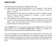
On the SD1104-E if you press the channel button (ie the 1,2) until the menu appears and then click in the position dial the scope will toggle that position dial between fine and coarse. With it set on coarse you should see the wave form quickly change between larger V/divisions.
You have the ability to set both frequency and level on the generator... and that is one reason for having a scope 😉 to accurately measure signal amplitudes.
If I had a digital scope I could tell you what to do, but I haven't. On analogue I would select 1 volt/division for the vertical scale and then increase the amplitude to give six squares of deflection (top to bottom) if I were using a X1 probe or simple lead. With a X10 probe (a divider probe) I would set the scope to 0.1volts /division
You should try and get in the habit of using the scope manually rather than relying on the auto feature as it will help you get a feel for levels and such like.
This image is from your scope manual and if this were set to 1 volt per division the amplitude here would be 5 volts peak to peak.
whay is the square wave challenging to the amp?
i can see what i was doing wrong now, i had it set at x10 so i wasnt looking at it correctly, thanks
Are you sorted now with that? You should be able to measure the voltage accurately enough just visually by looking at the deflection and working it out mentally... this is where analogue teaches you so much, you had to do it that way.
whay is the square wave challenging to the amp?
Have you tried it?
Imagine a 10 volt peak to peak sine wave. The peak is 5 volts and the RMS value is 3.53 volts.
The heating effect (how hot the load resistor gets) would be the same with 3.53 volts AC (rms) or 3.53 volts DC applied.
Now think of a 10 volt peak to peak squarewave. The load sees a steady voltage of either +5 volts or -5 volts across it. The power dissipated in the load is much more.
Squarewave testing is also tougher on the output stage as each half (the upper NPN or lower PNP output ) supplies either all or nothing to the load. The power dissipated can be more depending on level, so it gets hotter.
So always test at lower levels.
There is more... cross conduction of the NPN and PNP outputs where both conduct together because the transistors can not switch off quickly enough.
getting the hang of it a bit more now, but it has made me realise i need to carry on with my therory , so i am doing that each day now
Knowing the theory is hugely important and you are always learning new stuff and new tricks for testing and working on stuff.
You should try having a play with one of your amps and actually looking to see if you can crossover distortion as you reduce the bias current. It would need taking right down to practically zero to make distortion visible.
You should try having a play with one of your amps and actually looking to see if you can crossover distortion as you reduce the bias current. It would need taking right down to practically zero to make distortion visible.
well ive go enough i can try it on.
It is one of the things i am very interested in looking at with the scope
It is one of the things i am very interested in looking at with the scope
I would suggest if you try it to just link out the vbe multiplier on one channel of the amp. That will force zero bias without you having to alter anything.
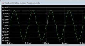
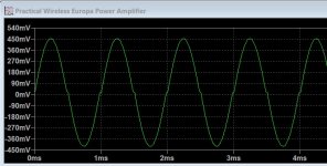
Test the amp at say 1 volt peak to peak output voltage (as low as that) into 4 or 8 ohms. Use a sine wave of between 1kHz and 10kHz.
It should look a bit like this which is a sim of the Europa amp at 10kHz and 1kHz. The distortion occurs at the 'zero' crossing point of the signal.
Test the amp at say 1 volt peak to peak output voltage (as low as that) into 4 or 8 ohms. Use a sine wave of between 1kHz and 10kHz.
It should look a bit like this which is a sim of the Europa amp at 10kHz and 1kHz. The distortion occurs at the 'zero' crossing point of the signal.
Attachments
Why are my images not displaying...
Edit. Dodgy link in post #47 🙂 Sorry JRE, it had to go. It was one these:
Corrupted thread?
Edit. Dodgy link in post #47 🙂 Sorry JRE, it had to go. It was one these:
Corrupted thread?
I would suggest if you try it to just link out the vbe multiplier on one channel of the amp. That will force zero bias without you having to alter anything.
Test the amp at say 1 volt peak to peak output voltage (as low as that) into 4 or 8 ohms. Use a sine wave of between 1kHz and 10kHz.
It should look a bit like this which is a sim of the Europa amp at 10kHz and 1kHz. The distortion occurs at the 'zero' crossing point of the signal.
ah right so thats what it will look like.so the worse it is the bigger the deviation will be as it crosses zero?
I would suggest if you try it to just link out the vbe multiplier on one channel of the amp. That will force zero bias without you having to alter anything.
Test the amp at say 1 volt peak to peak output voltage (as low as that) into 4 or 8 ohms. Use a sine wave of between 1kHz and 10kHz.
It should look a bit like this which is a sim of the Europa amp at 10kHz and 1kHz. The distortion occurs at the 'zero' crossing point of the signal.
not sure any of the amps i have here have a simple VBE multiplier, but i have a few where the bias can be adjusted via VR's so i can use one of those
Think theory 🙂
You normally have a driver transistor and an output in each upper and lower part of the output stage.
You know how much voltage you need to turn on a transistor (0.6v across base and emitter) and so you have four base/emitter volt drops to overcome. So there is a dead zone or dead band of 1.2 volts (for each upper and lower half of the stage) where the output devices don't conduct. That missing part is crossover distortion.
So why does it not look all that bad in a real amp if I just said you have a missing dead zone of -/+ 1.2 volts?
Answers on a postcard 😉
not sure any of the amps i have here have a simple VBE multiplier, but i have a few where the bias can be adjusted via VR's so i can use one of those
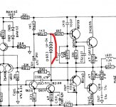
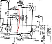
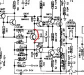
Most amps do have one although the NAD 3030 does not. That uses those four series diodes. You would just link the diode chain out on that one.
Usually 'shorting the multiplier' just involves linking the base of each driver transistor together so that no bias voltage can be developed between them.
Attachments
- Home
- Design & Build
- Equipment & Tools
- Siglent SDS1202X-E New to use of equipment.