afternoon all
I have been studying electronics on and off for about a year now and have been repairing old amplifiers with great success, however, as recommended by a few people including mooly, who have really helped me over the last months, its time i started using an oscilloscope as it will help me improve my deeper understanding when testing such items.
The thing is im having a bit of trouble getting started and would really use a bit of help.
I have done all the initial set up with the probes etc, so no issues there.
Its understanding the menus and terminology and what does what.
I would like some help to start with just some basic things i can do.
I have brought a signal generator, (TG 210) but i cant seem to get anything to register on the screen for some reason, so i guess its me and the way i have set it up maybe?
I have followed instructions, but some of the terminology goes over my head
Maybe there is a good online course someone can suggest? that really starts with the basics as i want to understand what i am looking at also when i do actually get to using it properly.
many thanks 🙂
Last edited:
I don't use a digital scope so the ins and outs of what buttons to press... well I would need it in front of me to be sure 🙂
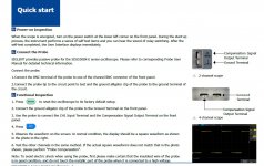
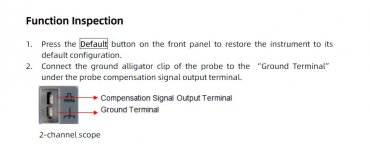
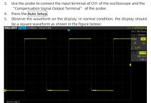
The first thing is to make sure you can get the 'cal' signal to display correctly. Have you tried that? Just connect Channel 1 to the Cal output on the front.
Can you get this far?
And from the main manual:
The first thing is to make sure you can get the 'cal' signal to display correctly. Have you tried that? Just connect Channel 1 to the Cal output on the front.
Can you get this far?
And from the main manual:
Attachments
OK, so what I would do now is repeat that exercise and this time, once you have the Cal waveform showing correctly you just disconnect the probe from the Cal signal and transfer it across to the signal generator. Probe ground to any BNC connector ground (the outer part of the socket) and the probe tip to the inner part of the socket.
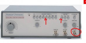
Press the 2K button and the Sine button. Set the Freq dial halfway round to '10' and have Symmetry in the middle. DC offset in the middle at '0'. Attenuator button not pressed in.
Turn the amplitude control up and down and see if the scope shows a signal.
Press the 2K button and the Sine button. Set the Freq dial halfway round to '10' and have Symmetry in the middle. DC offset in the middle at '0'. Attenuator button not pressed in.
Turn the amplitude control up and down and see if the scope shows a signal.
Attachments
yep did all that and nothing changed on the screen although i only has the '2' button pressed not '2k' (idiot pound)
i have the new BNC connectors now so i am going to try those tomorrow
i presume i just use the main outputs of the generator to the channel 1 connector
i have the new BNC connectors now so i am going to try those tomorrow
i presume i just use the main outputs of the generator to the channel 1 connector
Last edited:
I would keep the scope settings as they are for displaying the Cal signal. Get that on screen first.
Use the output that says 'Main Output'. The other one is a TTL/CMOS output (logic level output) and the other socket is to allow you to set or sweep the frequency from an external voltage you apply. You wont use either of those two at the moment.
Use the output that says 'Main Output'. The other one is a TTL/CMOS output (logic level output) and the other socket is to allow you to set or sweep the frequency from an external voltage you apply. You wont use either of those two at the moment.
Another Standard Check is to probe your finger with the sensitivity turned up. It will usually display big distorted 50/60Hz wave. (And you know that's not internal leakage or software bugs.)
Also tap your tuner/phono/iPhone audio. Useful for amusing stoners.
Also tap your tuner/phono/iPhone audio. Useful for amusing stoners.
I would keep the scope settings as they are for displaying the Cal signal. Get that on screen first.
Use the output that says 'Main Output'. The other one is a TTL/CMOS output (logic level output) and the other socket is to allow you to set or sweep the frequency from an external voltage you apply. You wont use either of those two at the moment.
so this is what i have, is this correct?
Attachments
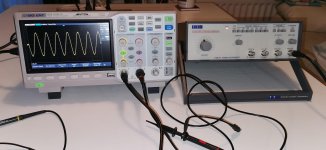
 that looks good.
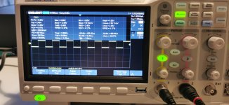
I would advise you get familiar with the basics now. You should be able to set the vertical controls manually to your chosen level of 'volts per div' rather than using the Auto feature.
The same applies to the horizontal settings which are time per division.
Have a play with those and try and calculate manually what you see. For example one cycle of the 1kHz sine you have in the picture takes up two squares horizontally. Look at any point on the sine and move along until that same point occurs. Count the squares.
So you have two squares horizontally per cycle. I know that for 1kHz that means each division is 0.5 milliseconds in time. That is the time it takes the 'spot' to travel from left to right to cover one cycle. Two times by 0.5 millisecond per division is 1 millisecond in total. That is per cycle.
We find the reciprocal (use a calculator using the 1/X function) which is just the time (1 millisecond) divided into 1. That will tell us the frequency.
So we get 1E-3 (or 0.001 if you prefer) divided into 1
1/0.001 = 1000Hz
Also you can try measuring the peak to peak amplitude of the sine. That is top to bottom. You will need to know the volts/div. Lets say you see 5 squares at 1 volt per division. That is 5 volts peak to peak.
If you measure that voltage on your meter (use an AC voltage range) you would see 1.76 volts.
Can you remember why?
(note... your meter may have reduced accuracy at frequencies above even a few hundred Hertz so if you try that and get odd results try using a lower frequency like 50 or 100Hz)
You can test your meter and see how the reading becomes inaccurate at higher frequency.
im a bit confused here by what i see on the scope.
If the peak to peak volts is 80mv wouldnt this be about 56mv rms? but on the screen it shows 31mv? my multimeter shows 35mv 🙁
I know they do 🙂 but its also good to know how to work it out. That gives you a feel for the quantities involved.
You could very carefully try applying that signal to an amplifier and have a look at the output. Set the amplitude from the generator to something much lower, say 1 volt peak to peak to begin with.
These are super useful to have a few of, BNC to phono adapters and also BNC to phono leads. You can connect the generator direct to an amplifier then.
https://cpc.farnell.com/vitelec/va206/adaptor-bnc-to-phono-socket/dp/CN11936?st=bnc to phono
https://cpc.farnell.com/pro-signal/psg00549/bnc-to-phono-plug/dp/AV14135?st=bnc to phono plugs
Maybe something to stick on the next order.
i ordered a pair of these earlier, i also got some replacement MJ15003G transistors for an amp im working on from CPC, first time ive used them, they seem pretty good.RS are very good, but also very expensiveI know they do 🙂 but its also good to know how to work it out. That gives you a feel for the quantities involved.
You could very carefully try applying that signal to an amplifier and have a look at the output. Set the amplitude from the generator to something much lower, say 1 volt peak to peak to begin with.
These are super useful to have a few of, BNC to phono adapters and also BNC to phono leads. You can connect the generator direct to an amplifier then.
https://cpc.farnell.com/vitelec/va206/adaptor-bnc-to-phono-socket/dp/CN11936?st=bnc%20to%20phono
https://cpc.farnell.com/pro-signal/psg00549/bnc-to-phono-plug/dp/AV14135?st=bnc to phono plugs
Maybe something to stick on the next order.
Last edited:
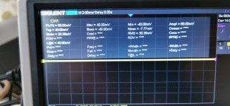
im a bit confused here by what i see on the scope.
If the peak to peak volts is 80mv wouldnt this be about 56mv rms? but on the screen it shows 31mv? my multimeter shows 35mv 🙁
80 millivolts peak to peak is 40 millivolts peak. Divide that by 1.414 to get the rms value which is 0.040/1.414 = 28 millivolts rms.
That is a very low value for most DVM's to resolve. You might get more accuracy at much higher voltage levels, say 10 volts peak to peak or more.
Try the attenuator on the generator. 20db attenuation should reduce the voltage by a factor of 10. So 10 volts peak to peak becomes 1 volt peak to peak when you attenuate it by 20 db.
CPC is part of Farnell, often a lot cheaper but they don't carry the same range. For common stuff they are great.
That peak voltage issue is why I'm looking at a TrueRMS 1000V capable multimeter (ie £120) the Black Friday sales instead of the trusty 1000V £30 multimeter. Before attaching the oscilloscope.
Looking good
Looking good
80 millivolts peak to peak is 40 millivolts peak. Divide that by 1.414 to get the rms value which is 0.040/1.414 = 28 millivolts rms.
That is a very low value for most DVM's to resolve. You might get more accuracy at much higher voltage levels, say 10 volts peak to peak or more.
Try the attenuator on the generator. 20db attenuation should reduce the voltage by a factor of 10. So 10 volts peak to peak becomes 1 volt peak to peak when you attenuate it by 20 db.
ok see what you mean
so my next burning question is then ,what am i seeing here.I thought when connected to the amp terminals i might get some 'live' info on screen including the voltage, but it appears this is not the case.
eg the centre was out by 35mv so i adjusted down to 0v, but nothing changed at all on the screen- so what am i looking at?
eg the centre was out by 35mv so i adjusted down to 0v, but nothing changed at all on the screen- so what am i looking at?
Attachments
......
eg the centre was out by 35mv so i adjusted down to 0v, but nothing changed at all on the screen- so what am i looking at?
Not a lot is the quick answer 😉
If you set the scope trace so it is centred with nothing applied to the probe (probe and tip shorted) that gives you a baseline to measure from.
If you DC couple the scope input then the trace should then shift up or down depending on the actual offset.
If you apply the generator output to one of the line inputs such as Left Channel CD input and turn the volume up a little then you should see the amplified sine wave appear at the speaker terminals.
Begin by testing with no load attached and keep the generator output low. If you turn the volume up and still can not see anything then you are doing something wrong. Turn the volume back down and recheck what you are doing.
- Home
- Design & Build
- Equipment & Tools
- Siglent SDS1202X-E New to use of equipment.