I may try bodging in a current source load on the input pentode, normally a bad idea (dueling current sources - duh duh duh duh dunn..). However, the extra load of the partial feedback resistor will likely make it possible. I'll try running it using the original schematic first, though.
I've CCS loaded several pentodes with great results (the cascode mosfets win the duel). The only issue I have experienced is plate voltage stability over time due to the high gain. With the 6EW6 equivalent I am using, I am running effectively fixed bias with a 3mA CCS in parallel with 1M and I see a good amount of plate voltage drift (50+V or so over the first ~20 minutes). As I stated above, this configuration has a gain of over 2000. Not a big issue for me as I made up some small bias servo boards a while back and these solve the problem nicely.
Earlier iterations had some degeneration in the input stage (cathode connected to feedback network like you are doing) and gain of ~500 and I saw no significant plate voltage drift over time.
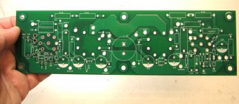
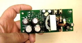
Here's the new board that just came in - different form factor. I'll be populating it and bringing it up in the coming weeks. I'll probably use a custom DC-DC converter run from a 24V SMPS for power rather than the original supply. As per usual, constructing a nice case will take the most time and effort.
Attachments
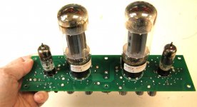
Here's the amp all stuffed and ready to go, except for the feedback components. I'll be running the beast with just the inner loop to start with and dial in some excess gain so I can use a bit of global feedback to stiffen up the XFMR response. Im building up the DC-DC converter so I can run the amp on just 24 VDC.
Attachments
Looks very neat!
I have a bunch of 807-clones (5B/255M) and am interested in circuits that get round the g2 limitation. Triode wired with the RH807 is one option, but your circuit is very interesting.
Regarding 400VDC and 200VDC B+ requirements. Would it be possible to use a voltage doubler to provide the 400VDC, and just take the 200VDC from before the doubler? Since the g2 supply will be so tightly coupled to the plate supply, does this reduce or increase the need for regulation of the g2 supply?
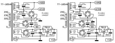
With a transformer from TubeTown it is easy to get two voltage. For a bit more use the 12V winding in series.Regarding 400VDC and 200VDC B+ requirements. Would it be possible to use a voltage doubler to provide the 400VDC, and just take the 200VDC from before the doubler? Since the g2 supply will be so tightly coupled to the plate supply, does this reduce or increase the need for regulation of the g2 supply?
Mona
Attachments
Thanks for the advice and the company suggestion. My son fancies a Champ style amp, and that site was ideal!
Ketje - I'm using an SMPS to generate both thee B+and the filament voltage. I'm putting the 6EW6 filaments in series, as well as the 6LC^Cs, and running both series strings in parallel. The SMPS is a custom DC-DC converter that will be powered from an external 24V switching adapter. This takes 1/3 of the weight out of the amplifier.
After some more thoght, you could use one of the old Fisher or Scott transformers that employed a doubler, but I want the SMPS route to save size and weight. The original Shrine amp fit into a 6" cube with tubes on top, the rest inside... That was mostly due to the SMPS.
After some more thoght, you could use one of the old Fisher or Scott transformers that employed a doubler, but I want the SMPS route to save size and weight. The original Shrine amp fit into a 6" cube with tubes on top, the rest inside... That was mostly due to the SMPS.
Last edited:
Why bother with DIY SMPS when you can get this:
DC-DC 8~32V to 45~390V High Voltage Boost Converter Step-up Booster. J7E1 U1P1 | eBay
If the spec;s are true, 390VDC @ 200mA, it's a bargain.
DC-DC 8~32V to 45~390V High Voltage Boost Converter Step-up Booster. J7E1 U1P1 | eBay
If the spec;s are true, 390VDC @ 200mA, it's a bargain.
I may try bodging in a current source load on the input pentode, normally a bad idea (dueling current sources - duh duh duh duh dunn..). However, the extra load of the partial feedback resistor will likely make it possible. I'll try running it using the original schematic first, though.
Ale over at Bartola has tried a pentode input/driver with a CCS load and using the feedback resistor to stabilise the operating point.
I think he had some success and some issues so he might be a source of valuable information.
t
Electrix -
I have almost 40 years of experience designing and building and testing SMPS (it's been my job since 1980), so I prefer to do it myself. That way, I know exactly what I'm getting.
I have almost 40 years of experience designing and building and testing SMPS (it's been my job since 1980), so I prefer to do it myself. That way, I know exactly what I'm getting.
Very interesting, exept the "powered from 24V adaptor".Ketje - I'm using an SMPS to generate both thee B+and the filament voltage. I'm putting the 6EW6 filaments in series, as well as the 6LC^Cs, and running both series strings in parallel. The SMPS is a custom DC-DC converter that will be powered from an external 24V switching adapter. -
I have almost 40 years of experience designing and building and testing SMPS (it's been my job since 1980), so I prefer to do it myself. That way, I know exactly what I'm getting.
If you could design a SMPS for B+ and filament off line, I think many tube builders would be interested.A bit more difficult for European 230V line.
Mona
I already have a line-operated SMPS that originally powered the Shrine. The rationale of using a DC-DC converter instead of AC-DC is to take the nasty safety interface out of the amp and use a DC source that is already safety certified. I would never market an AC SMPS because of safety and liability issues. In China, it's still the wild West, and they are shielded from liability by distance, governmental indifference, and anonymity
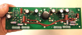
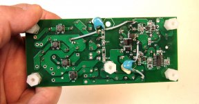
Here's the DC-DC converter in question populated and ready for test, using a current-fed push-pull topology. This module will supply plate, screen, and filament power using a 24V SMPS to feed the input. I've added some frills to quiet down the supply, which will make it to the next layout if they work.
Attachments
Why would you choose 1970,s SMPS technology (your first version), unnecessary complicated and difficult to tame? I'm also designing SMPS, possibly brought the first SMPS for tube applications (1997 off-line) on the market.Electrix -
I have almost 40 years of experience designing and building and testing SMPS (it's been my job since 1980), so I prefer to do it myself. That way, I know exactly what I'm getting.
BTW if you power that ebay SMPS from a traditional transformer based PSU, nothing can go wrong.
Nothing did go wrong.. I tried an RCC flyback for my first Shrine power supply, because I had analyzed RCC flybacks for years, but never built one. It worked OK once I solved some of the EMI issues, but I replaced it with a quasi-resonant flyback using the L6565 controller, improving EMI and efficiency.
The current fed push-pull is a natural for low voltage input and relatively high output power. I have used it in several applications already with great success, form a small unit powering a VT headphone amplifier to driving a thyratron blinker, also a similar amplifier than one shown here, but with a CF stage between the input and output tubes..
The current fed push-pull is a natural for low voltage input and relatively high output power. I have used it in several applications already with great success, form a small unit powering a VT headphone amplifier to driving a thyratron blinker, also a similar amplifier than one shown here, but with a CF stage between the input and output tubes..
Why bother with DIY SMPS when you can get this:
DC-DC 8~32V to 45~390V High Voltage Boost Converter Step-up Booster. J7E1 U1P1 | eBay
If the spec;s are true, 390VDC @ 200mA, it's a bargain.
... because unfortunately they are not that reliable in this duty. I had one fail after about 6months.
Shoog
... because unfortunately they are not that reliable in this duty. I had one fail after about 6months.
Shoog
I've been awaiting shipment on a few of these boards for something else, the cheaper non-split supply version. What was the failure mode you encountered? Any indication of what caused it heat, poor components, counterfeit parts, etc? They are rated at 200ma would running them derated 50% at 100ma have been better in your case? Is there a schematic anywhere floating around for these ubiquitous boards? Everyone seems to be selling them.
Last edited:
Couldn't say really, I just don't think they are that great at continous high power draw which is what valve amps sort of demand of them.
I was gutted because there are no good reasonably priced alternative SMPS for valve amps and I refuse to pay the stupid prices for Valve power supply Iron.
Shoog
I was gutted because there are no good reasonably priced alternative SMPS for valve amps and I refuse to pay the stupid prices for Valve power supply Iron.
Shoog
It looked like they were power-limited, not current limited @40W load power. You can't do 390V *and* 200mA at the same time.
That could be the problem right there, if you want to run them @50%, you are going to have to limit to 50mA or so at max voltage.
Back to the topic, wrenchone, do you plan on posting some measurements of the final amp? I'd love to see how it performs.
That could be the problem right there, if you want to run them @50%, you are going to have to limit to 50mA or so at max voltage.
Back to the topic, wrenchone, do you plan on posting some measurements of the final amp? I'd love to see how it performs.
- Home
- Amplifiers
- Tubes / Valves
- "Shrine" SE Amp using 6AH6 and 1625