Did anybody make some measurements yet of the Zo of a screen driven pp amp?
Testing I did about 5 years ago on an 80 watt 6AV5GA amp with no feedback seems to point to an output impedance equal to, or slightly higher than the same tube driven via G1 alone. I did not actually measure the Zo, just observed the output voltage drop when a resistor was switched in across the load.
More measurements are coming on the amp I have now, but I won't have time to power it up for a week or two. The plan is to apply local feedback around the output stage, or output and 2nd driver stages to see how the Zo is reduced.
I found a transformer to free up some top side real estate. The amp I'm chopping up for a chassis has a 65VCT transformer. Doubler for the G2 and center point of the doubler for bias.
Should get me ~180v to regulate for G2 and -90V for the bias. Of course, it's out if a 100W amp and big, but it fits in the slim profile of 1.5" inside the chassis.
Should get me ~180v to regulate for G2 and -90V for the bias. Of course, it's out if a 100W amp and big, but it fits in the slim profile of 1.5" inside the chassis.
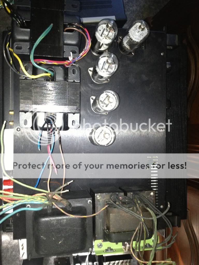
This layout gets the power iron away from the output iron and allows for some extra space for the caps to mount between the power and output iron. Look any better?
Look any better?
That's more like something I would do.
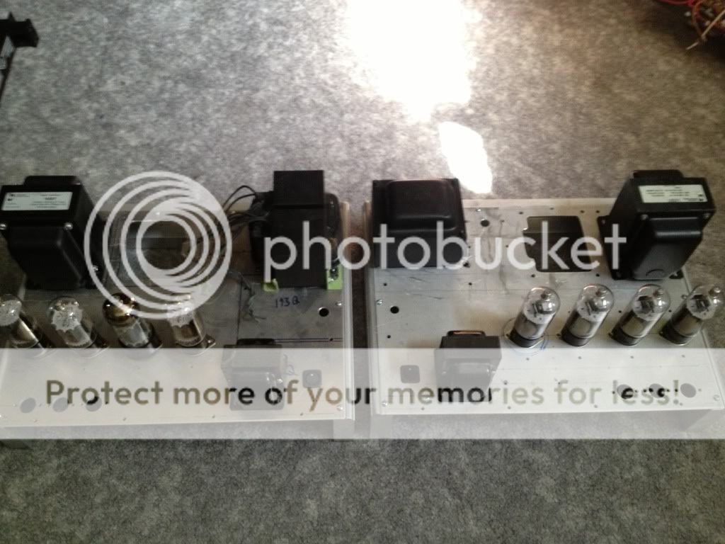
I have found that mounting the two OPT's in the same plane (rotation) doesn't provide a noticable degradation and looks better. In a stereo amp with both OPT's touching each other and lined up, I could just hear some faint bass from the speker connected to a channel with it's input shorted, while the other channel was driven to clipping with Depeche Mode into a dummy load. I suspect much of that coupling came through the common power supply.
Why 5 output tubes? One RCA and 4 Sylvanias.
Cool. That's something I was wondering about. I would prefer the bells facing the same direction.
Why 5 tubes? The last one is just to hold spares😉
Kidding. I had to order more sockets, and have no way to stand the other 3 up🙂
Why 5 tubes? The last one is just to hold spares😉
Kidding. I had to order more sockets, and have no way to stand the other 3 up🙂
572b Zero Bias amp.
Lots of chokes and separate Regulated supply for drivers.
phil
would like to see schema
I was loading a bunch of tubes into the car for their last ride....to ESRC, when I spotted a pair of 6BG6GA's. These were tubes that AES sent me by mistake when I ordered a bunch of 98 cent 6BQ6GA's several years ago.
For those who don't know, the original 6BG6GA and the 807 were made from the 6L6GA. The 807 got some extra shielding around the bottom and a different base. The 6BG6GA just got an octal base.
The 6BG6GA IS a re based 6L6GA.....but near the end of vacuum tube production some vendors, especially Philips ECG and Sylvania stuffed the glass with whatever they could find to fulfill government contracts. The oddest creation was the 6B4GA. It was a repined 6AV5GA, yes sweep tube guts inside a DHT envelope.
In this case Sylvania made some 6BG6GA's with 6L6GC guts, and some with 7027A guts. I opened these boxes, and they were identical, and they weren't ordinary 6BG6GA's they look like 6L6GC's inside, so the obvious question that needs to be answered is........
We all know...or should know, that ordinary audio tubes don't like screen drive. Being a bit slow and not always believing what I am told, I tried it years ago, and "they" were right. BUT, what about DUAL drive.....so I stuck the 6BG6GA's into the amp and cranked.....they 🙁 🙁 🙁 🙁
Wait a minute, no 6L6 type is going to like a 3300 ohm load with that wimpy little cathode. I rewired for 6600 ohms and CRANKED....and CRANKED.....🙂🙂🙂
How much power can you get from a pair of 6L6GC's???? Well despite the top cap and use in the sweep circuit of old B&W TV sets, they are not REAL sweep tubes, so they don't make sweep tube kind of power, but they do make 80 watts at the edge of clipping. The distortion just a bit below clipping is very good. It's 1.8% at 50 watts. No feedback at all.
These tubes drew no current at the same settings used for the 6CB5's. They needed much more screen voltage, no surprise there. I turned the screen supply up to 400 volts (previously 325) and lowerd the -80 volt supply to -65 volts. This made the mosfets hot, and the 10 watt screen resistors started smoking.
I left the amp at 80 watts for about 10 minutes. The tubes weren't excited but the resistors were hot enough to melt solder, so I stopped the test. The clipping observed at the output was caused by the screen running into the 400 volt supply rail. Plate voltage was 550 volts and more voltage did not increase power. More screen voltage would require different resistors and bigger heat sinks on the fets.
Game over for now, back to loading the car.
G1 & G2 drive
I don't know nothing but I think Mark Kelly suggested using a CCS loaded driver; using the low impedance source/cathode follower output to drive G2, and the high impedance plate output to drive the G1--with appropriate voltage scaling.
Might be summat to think about.
cheers, tim
I don't know nothing but I think Mark Kelly suggested using a CCS loaded driver; using the low impedance source/cathode follower output to drive G2, and the high impedance plate output to drive the G1--with appropriate voltage scaling.
Might be summat to think about.
cheers, tim
maybe close to mythbuster´s😀And now we return to "Cooking, with Chef George".
I cannot imagine what your lab smells like.
I plan to follow mr Tubelab's path, long tailed pair followed by a second long tailed pair.
The tubes I plan to design the circuit for is PCF80/82/802, depending on how much gain I need. (triode in first LTP, pentodes strapped as triode for second LTP)
To bring the Zo down, I'll try to use shunt feedback, a resistor from the output tube's anode to the driver's anode. Output tube I'm playing with is the PL300.
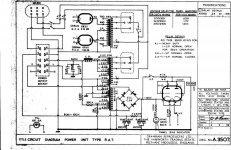
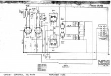
811A circuit
811A circuit as i built it. original Power supply circuit uses mercury vapour rectifiers I considered the Mv rectifiers would make the amp too big.
I used big toriodals and a bridge circuit; Choke input as you need very good regulation as you do with screen drive using EL509's as Zero bias triodes. I think best to use two heater supplies, so you can measure the current draw using two 10 ohm resistors to earth. Very important to have a slow turn on; protects the 6BL7's as the 811's /572b's heat up very fast, compared to the 6BL7's.
You could use sweep tubes instead of 811's, but when i tried them did not like the sound, at least with 811/572's you can use 70 ma current draw. 600 volts is the max with 811A's, less with 811's. 600 volts gives you 100 watts.
i have never tried using Mosfets instead of the 6BL7's as the 6BL's are cheap and trouble free. I regulated the driver supply, not sure if it is worth it.
Phil
Attachments
I did not think about these chassis at first, but they are ideal for this. Plenty of space, and I can just plate off the old power and output holes to mount these transformers.
I think Mark Kelly suggested using a CCS loaded driver
I have seen a few circuits that drive G1 and G2 simultaneously going back as far as WWII. I don't recall the configuration that you refer to, but I am using a pentode LTP driver that already has a CCS in the tail. A second CCS doesn't work, I tried it a few years ago. A triode driver does like a CCS load, but I need pentodes for these experiments. I may try to apply feedback to the driver screen grid.
.....pentodes strapped as triode for second LTP.....I'll try to use shunt feedback, a resistor from the output tube's anode to the driver's anode.
I have had dozens of people tell me how you can't apply plate to plate feedback to a triode, and many of the same people tell me not to call it Schade feedback, but I have tried using "Schade" with a triode driver and the results are mixed. Sometimes it works quite good, especially with a high Rp triode.
A voltage divider is formed between the feedback resistor, and the plate resistance of the triode in parallel with it's load resistor. The plate resistance of a triode varies with applied signal resulting in continually variable feedback. In some cases this can actually raise the distortion. In an LTP which has a fairly high output impedance, it usually works. You will just have to try it. Also try running the feedback resistor to the opposite pre-driver plates. This seems to cancel out some of the odd order crud created by unbalance.
And now we return to "Cooking, with Chef George"..... I cannot imagine what your lab smells like.
Essence d' Allen Bradley, vintage 1967.....a very good year🙂
Most of the time it smells like a 35 year old spare bedroom. Sometimes it smells like fear, apprehension, and respect, like when you are about to flip the switch on something big, and sometimes out of nowhere......the smell of exploded Nichicon......vintage 2011😡
Here in the US we have a 3 day weekend coming, so I should be able to try to make something smell good.....OK on the barbecue grill...and avoid feeding Kaptain Kilowatt any more Nichicon!
Last weekend it was.....wasted away in Margaritaville......eating my Cheesburger in Paradise......note the absence of the usual crowds on a Saturday afternoon. OK, just testing to see if a certain moderator was uh moderating......
Attachments

Tonight I put back the 6CB5's and tried twisting some knobs. It seems that my driver board is just not happy on 300 volts. It needs about 325 volts to work right. I need to see what my BFT will put out. I have been assuming 300/600 DC volts.
I set the controls for 150 watts output and just let it run for like an hour. After a while the hint of red plate shows in one output tube, and it's the one with the lowest current. Swap tubes, glow follows tube....OK need to try more tubes. I plan to switch over to a more modern 12 pin compactron that also has a 24 watt plate, and I have about 100 of them, so picking 4 good ones should be easy.
After the hour was up I noticed two more blue resistors had lost some of their color. I did the easiest possible thing, I simply snipped them out of the circuit....power went up....distortion went down....it's safe to assume that they weren't important.
I tweaked bias, power supply voltages, CCS currents, and swapped some tubes. I found a set up where the screen grid and the plate start to glow at the point the amp starts to clip. At this point the distortion is 4.6% and the power output is 182 watts.
I set the idle current at 20 mA per tube, an arbitrary number. Distortion at 1/10 watt is 1.01% The distortion is mostly hum and noise. Distortion at 1 watt is 0.62%. There is no feedback anywhere, but I plan to play with that soon.
I must also try some different tubes. I will rip up the octal output board to try some little tubes, and I just got to test the mighty 6LW6. If I can get over 200 watts per pair (should be easy) I can get 400+ watts from 4 and just match my BFOPT's. I also plan to build up a 12 pin output board and a 9 pin (13GB5) output board.
Awesome George! I'm going to go at this kind of slow. I am considering pitching the Hammonds for my Sowters on this since you are getting good figures. They are definitely better transformers.
LTP with CCSs
>>I have seen a few circuits that drive G1 and G2 simultaneously going back as far as WWII. I don't recall the configuration that you refer to, but I am using a pentode LTP driver that already has a CCS in the tail. A second CCS doesn't work, I tried it a few years ago. A triode driver does like a CCS load, but I need pentodes for these experiments. I may try to apply feedback to the driver screen grid.<<
Mr Tubelab, I dunno much but I understand CCSs can be used on the" top" and "bottom" of a LTP--even with pentodes. Morgan Jones describes something along those lines in his most recent book, and JC Morrison has some information that might be relevant at LabJC.com--right back at the 1st page.
best
tim
Current mirror on top maybe.
I had a similar idea for the second (driver) stage, here's what i've come up with so far.
(pnp darlington can be replaced by sziklai pair, or mosfet)
Attachments
- Home
- Amplifiers
- Tubes / Valves
- Show me your screen drive circuits