Can similar power be produced from a standard pentode arrangement vs. screen drive?
I now have essentially everything needed to start my build. My top caps came in today. I'd love to see what you can get out of 350V B+. Of course, I'm going to go with parallel pairs, so 50-60W per pair would be awesome!
I now have essentially everything needed to start my build. My top caps came in today. I'd love to see what you can get out of 350V B+. Of course, I'm going to go with parallel pairs, so 50-60W per pair would be awesome!
I am still working on the G2 supply. It does not need to deliver much current. My power transformer only has a single HV output secondary, so I think maybe adding another power transformer to deliver the G2 and negative bias voltage may be the best way to go.
I'm still trying to figure out what voltage to feed G2 also. George suggested between 150 & 175V.
I became fascinated with these sweep tubes from watching George's threads. I'm sitting on ~$2,500 in output iron at the house and I'm using the cheapest pair for these. Go figure.
I'm still trying to figure out what voltage to feed G2 also. George suggested between 150 & 175V.
I became fascinated with these sweep tubes from watching George's threads. I'm sitting on ~$2,500 in output iron at the house and I'm using the cheapest pair for these. Go figure.
you can try 150v gas regulators....like 0a2....
no need to go high on G2, lower voltage means lower drive requirements...
no need to go high on G2, lower voltage means lower drive requirements...
I will lay the chassis out and see what I want to do. There is a beefy toroid available surplus here that may work better for B+ giving me a ~450V @ 3A along with windings for neg bias.
The gas regulators are a cool idea. I'd like to do something a bit more adjustable though.
I'm using 8" x 18" steel plate 16ga for the top plate, so there should be plenty of room.
The gas regulators are a cool idea. I'd like to do something a bit more adjustable though.
I'm using 8" x 18" steel plate 16ga for the top plate, so there should be plenty of room.
Uhmm. you could do. a tube regulated Supply. A single pass tube. preferably a triode or a trioded sweep tube. 6au6 for error amp and a cathode reference whit a gas tube 5651 comes to mind.
you can add a pot and make it adjustable. Can't go below 135 volts without a negative reference though. As most pass tubes tend to need -40 volts to cut off.
you can add a pot and make it adjustable. Can't go below 135 volts without a negative reference though. As most pass tubes tend to need -40 volts to cut off.
There is a beefy toroid available surplus here
Could you be more specific. I got a big Tortran toroid surplus from Ebay that I plan to use in my amp maybe it's the same one?
Hi George,
It's from Apex Jr.
Keen-Ocean
162Vct 6A, 17V .2A, 24Vct .25A
I can put a doubler on the 162V winding a cap off the CT for ~450V, the wire the other two windings in series for ~ -55V.
I can put a regulator on my other transformer that would then be used solely for filament duty even though it has a 260V 4-6A winding also. I will try to clean up and lay some parts out today so you can see what in working with.
How many mA per tube is needed for G2?
I found a nice little shunt using the IRF610 on tubecad good for 50mA. I could use two of them for 50mA per pair.
Thanks!
Blair
I found a nice little shunt using the IRF610 on tubecad good for 50mA. I could use two of them for 50mA per pair.
Thanks!
Blair
I can put a doubler on the 162V winding
You will only get 2.8 X the 162 volts with no load on a doubler. My experience with load is 2.4 to 2.6 X the input voltage depending on load and transformer losses with silicon rectifiers.
I run a voltage doubler from a 480 volt transformer in my 845SE amp. It uses 5AR4 rectifiers and I get 1250 volts with no load and 1050 volts with 200 mA load.
The transformer may deliver well above 162 volts though. The transformer I have is supposed to deliver 390 VCT at 1.5 A. I get 420 VCT at about 400 mA.
How many mA per tube is needed for G2?
I have found that the screen current is inversely related to plate voltage. This is actually shown in the Sylvania 6CB5A data sheet plate curves. For a screen voltage of 150 volts, and any reasonable plate voltage (100 to 400 volts) the current is shown as under 5 mA per tube. I would allow for 15mA (the limit on the curves) during transients. The screen current will spike during the brief instant the plate voltage swings near zero on music peaks. Both sides in a P-P pair will not draw peak screen current at the same time.
The Sylvania curves also show screen driven data. For low plate voltages, under 50 volts the screen current curves stop at 140 mA and 175 volts.....I guess the screen is melted by then.
The tubes in my breadboard are branded "El-Menco" but they are Sylvanias.
Thanks George!
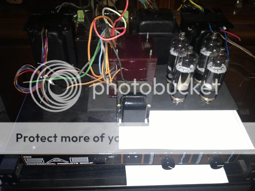
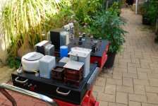
Does this layout look OK?
Or, is that transformer bundle too tight? They managed to get "bigger" when I put them on the chassis🙂
I guess I could use as mall transformer backwards off the filament winding and rectify that for the G2 supply.
Does this layout look OK?
Or, is that transformer bundle too tight? They managed to get "bigger" when I put them on the chassis🙂
I guess I could use as mall transformer backwards off the filament winding and rectify that for the G2 supply.
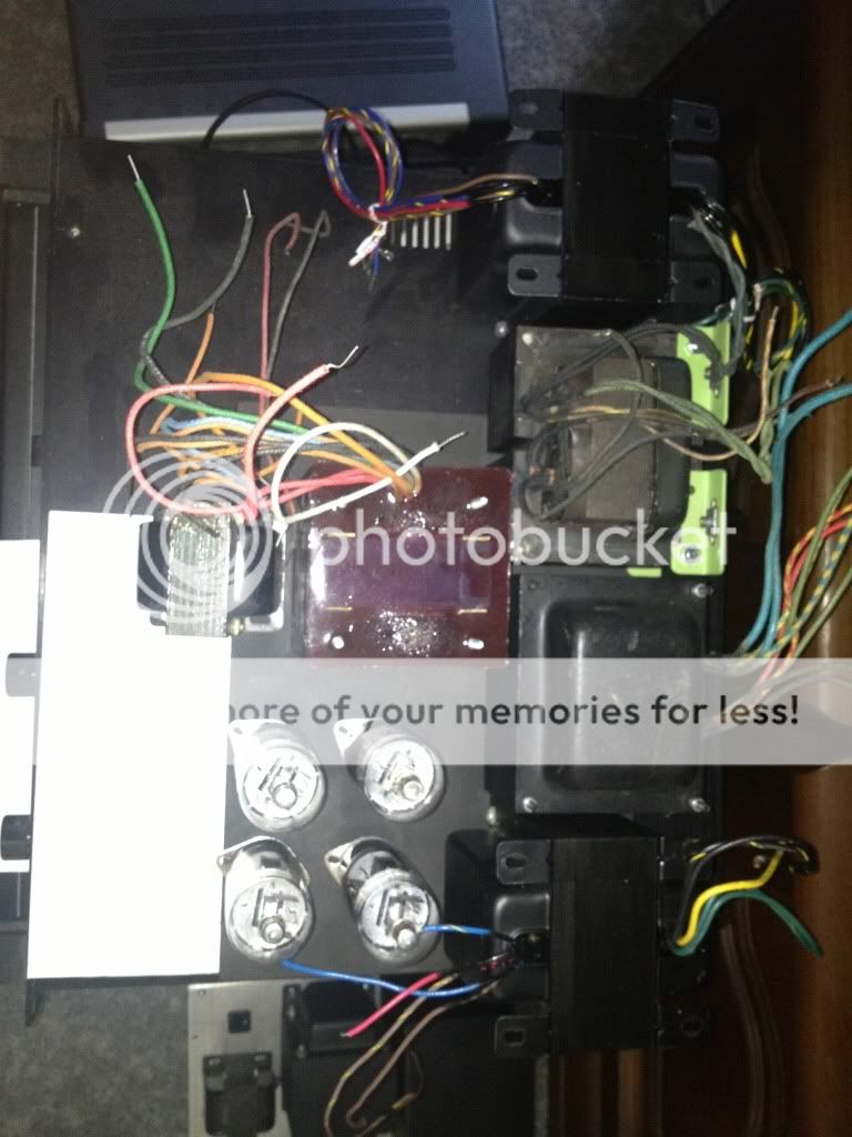
Or this? It's an old SAE amp that works, but I have no use for. Easy to guy, and repurpose upside down so the bottom is removable.
This would have shared G2 and bias supplies, but separate filament and plate supplies.
It's a big chassis with a bit of real estate, but not very tall.
This would have shared G2 and bias supplies, but separate filament and plate supplies.
It's a big chassis with a bit of real estate, but not very tall.
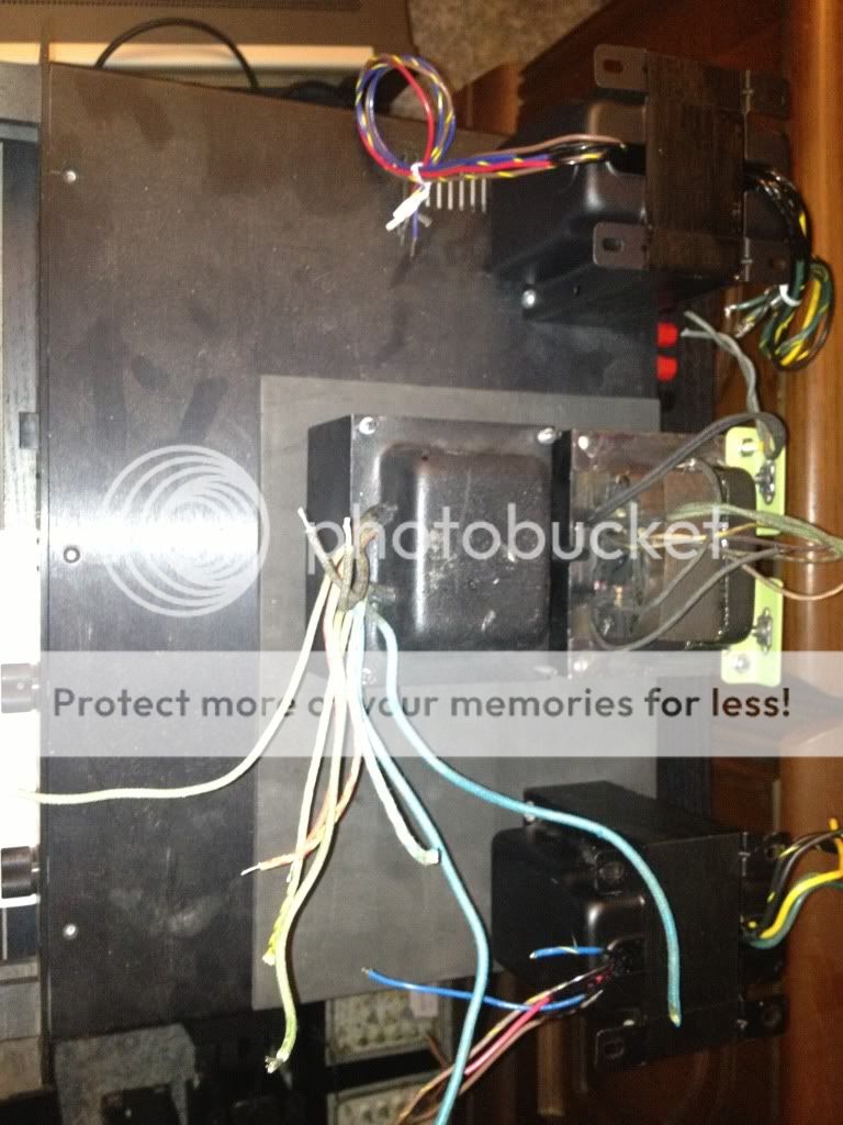
The transformers need some room around them for magnetic isolation and for air cooling. You don't want the tubes too close to them either. Might get away with the smaller chassis if the three big xfmrs were along the long edge with the small xfmr stuck underneath, and then the tubes lined up along the other long chassis edge. Will still be tight though probably. Room for electrolytic or oil caps? Inductor? Power line filter? Fuse? Knobs, connectors.
Last edited:
Power transformers can often be right next to each other with minimal interaction. If the stray fields from one power transformer induce a few mV of hum voltage into a neighboring power transformer, who will notice.
The OPT however is a different matter, those few mV go directly to your speakers, they do not pass GO, nor go to Jail! Even crappy speakers will hum.
The only true way to test for hum is to power up all the PT's and connect the OPT secondary to a speaker or scope. Ideally the PT's should have some load, at least tube heaters. The hum will be worse case with the OPT primary unconnected. Move all the transformers around to minimize coupled noise and hum into the OPT. Usually mounting the OPT at a right angle to the power transformers is best, but you have one horizontal mount PT. They can be a wild card.
Will the Keen-Ocean BFT fit under the chassis in any of your possible layouts? Maybe a small Antek toroid can be placed under the deck for heater, bias, or screen supply, or two of them for all 3 supplies. I am also considering a small SMPS for the heater supply in my amp if adding an extra winding to my surplus BFT doesn't work out. I ask these questions in an attempt to reduce the number of transformers in your amp.
I believe it would be possible to run two channels of an amp like you propose from just two Antek toroids. A pair of AN64115's would give you 4 X 115 volt 2.6 AMP! secondaries. 2 X 6 volt 5 amp secondaries, and 2 X 12 volt secondaries. Stick a bridge and cap on each 115 volt secondary. That will give you 4 X 160 volt unregulated supplies at well over 1 amp each. Use one for -160 volts, regulated down for bias. Wire the other 3 in series for 0, +160 volts, +320 volts, and +480 volts. Regulate the 160 (or 320) volts down for the screen supply, use the 320 supply for the driver, and use 480 for the plate supply. Wire the 6CB5 heaters in series pairs off of 12 volts, arranged so one open heater takes out the other tube in the P-P pair, and use the 6 volt windings for the driver tubes. Pete's little red driver board would make a good choice here, but it may be too big. A pair will not fit in my amp with the added mosfet board for screen drive.
I have a pair of really big toroids with dual 120 volt secondaries that I am planning to use for a 800 watt to 1 KW level sweep tube amp in the future. 4 X 160 volt supplies all wired in series to provide 640 volts to 4 or 6 X 6LW6's per channel. The OPT's are even bigger Plitron toroids rated for 400 watts at 20 HZ!
I will be away from this forum until late Sunday. I have to go to Orlando.😛 First stop.......Tube shopping at ESRC. No cash.....I trade Stan a car load of tubes I don't need for a few that I do need. Where do you think I got all the 13GB5's😀 Second stop......Saturday, I get to act like a 60 year old kid at Universal Studios.....Transformers 3D....... Last time Sherri just watched and shook her head, Harry Potter made her sick. I hate giving Comcast any more of my money, but I didn't buy the tickets.
Hi George,
I will try to find a small Antek or similar for bias and G2.
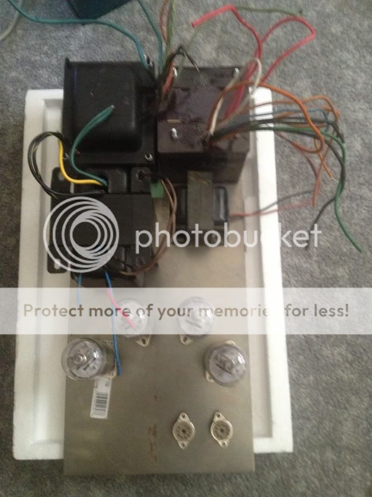
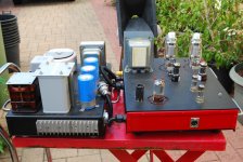
Of the transformers in this image, the power transformers are both identical. Just one has the end bells off in the image. Both have two 7A 6.3v windings, and a 250V winding at some stupid current. Each one ran 8 x 8417s in fixed bias for 200W. Bogen claimed his power transformers to be rated at 100% duty cycle. These were from industrial amplifier/modulator duty, so they are probably pretty tough.
I can always pull the bias the way he did with a backward diode and voltage divider, but isn't it best for the bias to hold steady even under extremes?
The other two transformers were just the auxiliary transformer to get bias and G2 voltage and a choke for a choke regulated G2 supply. I can use something like this to regulate G2 and tuck it under the chassis.
Shunt Regulators
I will try to find a small Antek or similar for bias and G2.
Of the transformers in this image, the power transformers are both identical. Just one has the end bells off in the image. Both have two 7A 6.3v windings, and a 250V winding at some stupid current. Each one ran 8 x 8417s in fixed bias for 200W. Bogen claimed his power transformers to be rated at 100% duty cycle. These were from industrial amplifier/modulator duty, so they are probably pretty tough.
I can always pull the bias the way he did with a backward diode and voltage divider, but isn't it best for the bias to hold steady even under extremes?
The other two transformers were just the auxiliary transformer to get bias and G2 voltage and a choke for a choke regulated G2 supply. I can use something like this to regulate G2 and tuck it under the chassis.
Shunt Regulators
- Home
- Amplifiers
- Tubes / Valves
- Show me your screen drive circuits