Either BJT could breakdown and would not short the supply to any grid.
This is true in your circuit. Much of this threads discussion has been centered around a conventional drive circuit possibly augmented by a mosfet follower. In that case a shorted device makes life rather unpleasant for the output tubes.
Most sand state devices fail to a short. The short may become an open if the short circuit current is high enough. In my G1 tied to G2 experiments the TO220 devices just became a black stain on the heatsink!
I have not given much though to your shunt regulated screen drive idea....yet. I have too many untested ideas of my own to blow up right now!
I did some expeimentation years ago with tubes and sand wired together in a "darlington" type configuration. I think that the tube/BJT pair sounded better than the tube/mosfet, but the tube/BJT didn't live through my torture testing while the tube/mosfet did. I think the kick back from the OPT and possible saturation was what killed the BJT's. I was using On Semi MJW21196 (250 volt, 200 watt) which were the biggest BJT's that were available at the time.
Q2 has 40V on the collector at all times. No reason it couldn't be MOSFET.
As for your SOA's, need a resistor in series with each collector to cut a big
cookie bite out of the grey....
As for your SOA's, need a resistor in series with each collector to cut a big
cookie bite out of the grey....
Last edited:
Here is the iron I have laying around without having to it more. I think this will work for conventional G1 drive.
The transformer with the doubler has two 13-14A 6.3V windings.
So, I can build two monoblocks using a quad of 6CB5s per monoblocks into the 1650T.
The transformer with the doubler has two 13-14A 6.3V windings.
So, I can build two monoblocks using a quad of 6CB5s per monoblocks into the 1650T.
I have not given much though to your shunt regulated screen drive idea....yet. I have too many untested ideas of my own to blow up right now!
Doesn't stop running the sim for curiosity sake. Seriously,
if not for that specific tetrode recommendation and .inc,
I couldn't have shown you anything even close to working.
Class A shunt is not the sort of thing that promises to be
efficient in delivering large grid currents to other valves.
And the concertina currents border upon the absurd too.
Even without blocking, look how big the coupling caps
have to be for 20Hz. And the iron simulates miserably
as well, that could just be the lack of a good subcircuit.
Would be fine for a little amp, especially guitar.But does
not strike me as a plan that scales up well.
OK, I am assuming that deicide67 is now talking about conventional G1 drive since that appears to be his current choice of design.
AJT is referring to screen drive, and all his comments are generally valid with a few exceptions:
If using a mosfet to drive a tube grid directly (either grid) a zener from gate to source is required. Many fets have them built in. The gate - source voltage rating may be violated without this protection during warm up.
The typical bias pot is connected to the gate of the fet, while the source of the fet is connected directly to G1 or G2 (or some combination of grids) of the tube to be driven. The bias pot sets the fets gate voltage, which controls the source voltage in a follower, which IS the tubes grid voltage, thus setting the tubes idle current. This is true regardless of which grid or grids are being controlled.
The mosfet current is set by the resistor connecting the source of the mosfet to the negative supply voltage. Despite one of my early screen drive circuit diagrams that I posted that does not have a resistor, a resistor should be used to set the minimum mosfet current, however the minimum mosfet current requirement has nothing to do with capacitance effects.
Many if not all mosfets and vacuum tubes lose transconductance at low currents. High transconductance is the main reason for choosing a pentode over a triode, and a mosfet over a tube for follower duty.
I have discovered another reason. Mosfets do unexpected things when transitioning through cutoff. The most common ugly thing is a quick burst of high frequency oscillation often well into the HF or VHF region of the RF spectrum. I have seen an amplifier that plays very well, sounds good, and measures good, but blanks out a TV set in the same room! Forcing a minimum current, even when the tube it is driving is cutoff is a good thing. Ferrite beads and stopper resistors are your friends.
Note that some purists will replace this resistor with a CCS to keep the fet current constant. This keeps the Gm constant which in theory is good, but I can hear no sonic benefit, so I don't do this, but you may feel otherwise. Remember that a CCS is just a specially doped high Gm fet that will oscillate if given half a chance. Tying two high Gm fets to the grid of a high GM tube is asking for a TV jammer!
Yes, the maximum current is limited by the size of the heat sink, and higher current may be of some value. Each case is different, depending on the grid current being drawn by the tube. I have 4 really BIG fets mounted to a really big heat sink to explore this area.....and to test them as output devices.
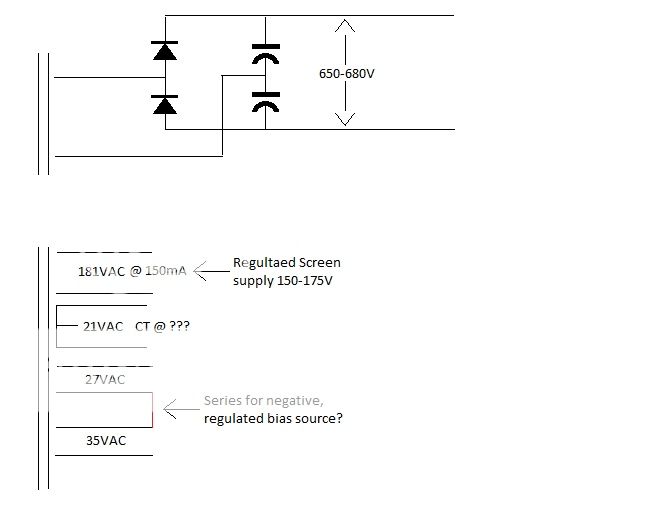
The positive supply voltage on the fet should be 20 to 50 volts above the expected maximum voltage needed by the grid being driven. A conventional G1 driven amp can probably work OK with 50 volts or so, but I typically use a +/- 150 volt supply for the fet since this is easy to make from a cheap isolation transformer, unless some other source is available in the amp, OR the tube requires more positive G1 voltage, like some transmitting tubes.
Some screen drive amps may work OK on a 150 volt mosfet supply, but many require more voltage. You want enough voltage to fully saturate the tube, plus the headroom in the fet. Some tubes need more than 150 volts to saturate them, especially if a slight negative G1 voltage is applied to lower distortion. The 6AV5 needs quite a bit more voltage. I think I needed 300 or more volts in my screen drive experiments with those.
Well, technially not Miller, since there is no voltage gain, but the input capacitance can go wild and more important CHANGES with applied voltage, if there is not enough voltage across the fet. This is one of the main arguments in the SS VS tubes debate (PIM caused by VVC effects) but do you know that a tube exhibits the same (albeit much weaker) effect due to the varying size of the space charge cloud with applied negative grid voltage?
A BJT does work, and I have used them. In some circuits they MAY appear to sound better....but second breakdown and SOA requirements cause them to rapidly turn back to sand when the Big Dumb Blonde One plugs in his guitar and cuts loose. When the BJT or mosfet shorts, the collector (drain) supply gets connected directly to the grid of your tube, and...it really doesn't like this!
Which, reminds me.....put a fuse or a small sacrificial resistor in series with the cathode...or at least the B+ lead of the OPT. Beware the typical glass fuse explodes violently on 650 volts into a shorted cap!
A zener and resistor, or a VR tube and resistor is sufficient for bias supply regulation, and SG supply regulation in small tubes like the driver. The screen current in an output tube can vary over a rather large range, which may be too much for a simple resistor - zener string to handle. A mosfet follower on the zener string can fix this. For an excellent example, copy the screen regulator from Pete's big red board.
If you use a conventional G1 drive circuit (no mosfet) the voltage and current requirements are similar to any other big output tube. The voltage required to fully cut off any given tube can be determined from the curves, and the bias supply should be able to achieve this voltage. The curves for a 6CB5 show cutoff reached at about -50 volts for a G2 voltage of 150 volts. Curves for other G2 voltages are not given, but cutoff will require more negative voltage for a higher screen voltage.
If a mosfet (or cathode follower for tube purists) is used to drive G1 then the current required for each mosfet is added to the negative bias supply requirements, AND to whatever positive supply feeds the drains of the mosfets.
Horizontal sweep tubes have a few advantages over the typical audio output tube:
The screen voltage requirement is low. This may be a disadvantage to some, because it rules out UL and usually triode, and often requires an additional power supply. If the plate voltage is considerably higher than the screen voltage (usually the case) the screen current is low, often under 10 mA. This is what allows screen drive.
The peak current capability is much higher. This makes for unmatched transient handling. It's easy to figure this out. Compare the size of the cathode in any sweep tube to the cathode in a 6L6GC. Which one do you want kicking your woofer around?
A sweep tube can usually be fully saturated without driving G1 positive. Have you ever heard of a sweep tube amp running class AB2? I have found no need to do so. Given proper choices of operating points you can get plenty of power without going into positive G1 territory. This means that mosfet drive is usually not needed.
WHAT???....Yes I have always been a big proponent of mosfet drive, I even call is PowerDrive and use it for most everything I build, but after spending almost 2 years annoying my neighbors with one of Pete's big red boards, and even playing my guitar through it, I have never heard it display any overload recovery effects often heard when overdriving a typical cap coupled audio amp. Note, this may be due to the fact that it has way more power than I need......SO...
I have set up my breadboard so that I can explore the effects of mosfet drive VS conventional RC coupling to the output tubes by swapping out the driver boards leaving the rest of the amp the same. I have a pair of Pete's driver boards set up so that they can deliver 7 watts of power if connected directly to an OPT. That is plenty of drive, it's just RC coupled. They will be compared against other driver boards, and maybe even the same driver boards with an external mosfet board if time permits.
Given that deicide67 probably doesn't want to wait until all these experiments are done to start building, what does he build?????? Well with 600+ volts, 8 X 6CB5's and some 1.9K OPT's, that combination should be capable of say 1.21 Giggowatts of power. A simple G1 driven circuit without mosfets should have no problem driving it to well beyond the OPT's capability, why build more? That's just my first guess though.
I should have some time to play this weekend...still to soon to know how much yet though, but I may be able to fire up something......its been far too long since I fried any parts!!!!!
thank you very much George i think i have all the info i want to hear from this latest post....your posts and that of SY's gives me the confidence to embark on this new frontier on my tube journey....
I know I'm all over the place here considering this is supposed to be a screen drive thread🙂 , but what about transformer based phase inverters? I've heard of using an output transformer primary as a phase inverter.
Any pluses, minuses to using iron phase inversion?
I have cheap access to a pair of Fisher X-100 outputs.
Thanks!
Blair
Any pluses, minuses to using iron phase inversion?
I have cheap access to a pair of Fisher X-100 outputs.
Thanks!
Blair
your posts and that of SY's gives me the confidence
I searched up some of my old stuff on this forum to see just how long it's been since I played with screen drive.....over 4 years. So there is some fog in the memory banks that needs to be cleaned out by blowing up a few parts 😀
While searching I did find some more relative threads.
Here I explored the upper limits of power from small tubes using screen drive, and discovered how, and WHY it is possible to blow the screen grid out of the tube. Short thread !! see post 4 and 5:
http://www.diyaudio.com/forums/tube...-p-p-experiments.html?highlight=tube+sale+AES
The concept of driving G1 and G2 simultaneously was explored in this thread with a basic working amp running in posts 19 and 20. No further work has been done since then.
http://www.diyaudio.com/forums/tube...-strawman-design.html?highlight=tube+sale+AES
Back in 2008 AES decided to clean out their warehouse by selling tubes for CHEAP. 6CB5's were $2 each and 6BQ6's were 98 cents.....this kicked off a buying and TESTING frenzy that involved screen drive and blown parts!
http://www.diyaudio.com/forums/tubes-valves/128533-tube-sale-aes.html?highlight=tube+sale+AES
Most readers here already know about Pete's big red board, but I took Pete's 18 WPC board and squeezed 250 WPC from it with minimal modifications. 250 WPC is probably on the edge of blacking out the whole block, but the 125 WPC version works great, and is quite reliable. In fact it has been rattling the house non stop for the last 4 hours by collecting the live audio feed from the Lollapalooza concert in Chicago and stuffing it through my 15 inch coaxials with 96db sensitivity. My neighbors aren't home, otherwise they would be hearing Nine Inch Nails. I have been up against the rails at a Metallica show, and this thing is louder......except for the PYRO! Very long thread....but lots of sweep tube testing, all G1 driven with no mosfets.
http://www.diyaudio.com/forums/tube...power-amp-design.html?highlight=tube+sale+AES
I give up and go with followers like everyone else.
Makes coupling cap sizes much more reasonable.
Also makes my Vocm regulator and EqualZ split
pointless features that don't serve any real need.
Ignore that for now...
My point this post is regarding a positive bias on
G2 and a negative bias on G1 at all times, avoids
0 crossing where the current suddenly changes.
-12.6V G1 just barely works for this tetrode at
350V Plate. G2 swings low enough to almost cut
off the BJTs. Even if I push it harder and do go
a little negative, the tetrode cuts off first, so
that's maybe not a huge problem...
Even with extremely well regulated common mode
screen voltages, cathode quiescent seems very
sensitive to small variations of plate voltage. Is
that a normal consequence of this tetrode type?
I thought if the screen was sensitive, that made
the plate less sensitive. What am I missing???
---
Q2 Note: Q2 doesn't exist, try M1.
M1 holds Vocm (at G2's) at +64.5V
Attachments
Last edited:
Some of the sweep tubes have an Rp in the range of 10K Ohm or even 5K..... Check the datasheet curves.
Rp was nominally 8K according to the datasheet.
As long as G1 and G2 are held steady, I would
expect that 8K means 8k slope looking into the
plate regardless of how its strapped to be driven.
But maybe that's not what 8K means...
And messin with winding ratios in the sim, it
still seems to favor 5K plate to plate, go figure...
As long as G1 and G2 are held steady, I would
expect that 8K means 8k slope looking into the
plate regardless of how its strapped to be driven.
But maybe that's not what 8K means...
And messin with winding ratios in the sim, it
still seems to favor 5K plate to plate, go figure...
Last edited:
Excepting triode strapped to the plate of course...
Datasheet doesn't even show curves for a normal
G2=Plate triode strapping, so I doubt that's where
8K comes from... Only curves G1, G1=G2, or G2
Sweaty EL509/6KG6 to be specific
Datasheet doesn't even show curves for a normal
G2=Plate triode strapping, so I doubt that's where
8K comes from... Only curves G1, G1=G2, or G2
Sweaty EL509/6KG6 to be specific
Last edited:
The OP has not been here in almost 2 weeks and his OPT's were up for sale, so I must assume that his sweep tube amp design is on hold or cancelled.
I have been slowly wiring things up in my spare time, and had started wiring one of Pete's red driver boards up to an octal output board to melt some 6CB5's since that's where I was going when I put things on hold to deal with the warehouse closing....about a year ago.
Since driving 6CB5's in G1 drive mode is no longer relevant I put the red board aside and finished up my new driver board. It was designed for screen drive, cathode followers, and just about anything else.
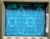
I made 3 boards, one to blow up🙂 and two to put in an amp that I am making. Last night I succesfully made smoke come out of board #1. In the process I made about 250 V P-P of drive (just starting to clip), and this was from a 450 volt supply. The plan is to run the driver tube plates from the 650 volt supply for the output tubes. That should allow for 400V P-P of clean drive. The upper 3db point is 450 KHz at 200V out.
The board uses two triode - pentode tubes in the 9DX pinout. There are 21 different tubes that will plug into this board. I have only tried one type. The two triodes are wired as an LTP with a CCS in the tail. They are direct coupled to the pentodes, also an LTP with a CCS in the tail. The pentodes outputs are AC coupled to mosfet source followers with 4 amp capability. Some screen grids are going to DIE!
I previously stated that I would start a new thread when I flip the switch on the 1KW plate supply. I am not there yet, so I am posting here. I will do a bit more testing on the driver boards before connecting up some output tubes and really making something glow!
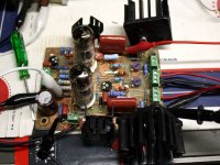
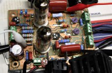
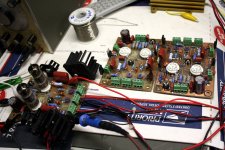
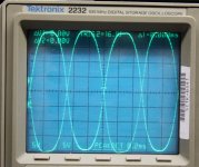
During testing I kept smelling something getting very hot. None of the semiconductors or big resistors were overheating, and there was no smoke......Until...... notice the blue 2 watt resistor in the upper right near the black trimmer pot. Can you tell what the color bands are? It was a 24K resistor. Due to some blonde arithmetic that 2 watt resistor was dissipating 9 watts. It finally started smoking and the board quit working, after over 1 hour. I think it's dead now! The 10K 3 watt resistor below it (in the row of 75K's) doesn't look so good either.
There are 4 pictures. The new board, a closer look, 3 of the boards, and a scope plot of 250 V P-P.
I have been slowly wiring things up in my spare time, and had started wiring one of Pete's red driver boards up to an octal output board to melt some 6CB5's since that's where I was going when I put things on hold to deal with the warehouse closing....about a year ago.
Since driving 6CB5's in G1 drive mode is no longer relevant I put the red board aside and finished up my new driver board. It was designed for screen drive, cathode followers, and just about anything else.
I made 3 boards, one to blow up🙂 and two to put in an amp that I am making. Last night I succesfully made smoke come out of board #1. In the process I made about 250 V P-P of drive (just starting to clip), and this was from a 450 volt supply. The plan is to run the driver tube plates from the 650 volt supply for the output tubes. That should allow for 400V P-P of clean drive. The upper 3db point is 450 KHz at 200V out.
The board uses two triode - pentode tubes in the 9DX pinout. There are 21 different tubes that will plug into this board. I have only tried one type. The two triodes are wired as an LTP with a CCS in the tail. They are direct coupled to the pentodes, also an LTP with a CCS in the tail. The pentodes outputs are AC coupled to mosfet source followers with 4 amp capability. Some screen grids are going to DIE!
I previously stated that I would start a new thread when I flip the switch on the 1KW plate supply. I am not there yet, so I am posting here. I will do a bit more testing on the driver boards before connecting up some output tubes and really making something glow!
During testing I kept smelling something getting very hot. None of the semiconductors or big resistors were overheating, and there was no smoke......Until...... notice the blue 2 watt resistor in the upper right near the black trimmer pot. Can you tell what the color bands are? It was a 24K resistor. Due to some blonde arithmetic that 2 watt resistor was dissipating 9 watts. It finally started smoking and the board quit working, after over 1 hour. I think it's dead now! The 10K 3 watt resistor below it (in the row of 75K's) doesn't look so good either.
There are 4 pictures. The new board, a closer look, 3 of the boards, and a scope plot of 250 V P-P.
Attachments
Hi George,
I haven't given up or cancelled the project. I just got different iron🙂
I got a pair of Lundahls that have a more appropriate 2.5K load for a pair of 6CB5A tubes. Lundahl says that they handle 210mA per side on the primary side. Will that be OK?
Thanks!
Blair
I haven't given up or cancelled the project. I just got different iron🙂
I got a pair of Lundahls that have a more appropriate 2.5K load for a pair of 6CB5A tubes. Lundahl says that they handle 210mA per side on the primary side. Will that be OK?
Thanks!
Blair
I haven't given up or cancelled the project. I just got different iron
Sorry, I saw something in one of the threads, maybe the Lundahl thread about a quad of KT88's.
2.5K is closer to the 3.3K that i have been experimenting with. It may be OK, depending on your B+ and power output requirements. I have smelled the smoke of burnt parts, so I expect to find a bit more time to play with this stuff in the near future. I have some 2.5K OPT's, maybe I will test some 6CB5's. It all depends on how things go in the fried stuff depertment.
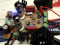
I will swap out the two toasted resistors with different values tonight and retest. I expect a few more days of optimizing the first driver board, then modifying and testing the other two boards. Then I want to test the pair of octal driver boards that haven't seen power in several years. They should work. I have one of Pete's little red boards that works, and another that is built but untested. I have 3 dual tube turret boards from AES to use for output tubes. 9 pin novar, octal and 12 pin compactron sockets can be swapped into them.
After all that stuff works I plan to play musical boards and tubes to see just what works well together. I can easilly test 1250, 1650, 2500, 3300, 5000, and 6600 ohm loads with minimal difficulty at 200+ watt power levels.
I made a few charts of just how to wire tube sockets for maximum swappability. With proper wiring there are 11 different tubes that can be plugged into the same socket as the 6CB5. I have 7 of them, so that configuration is pretty high on the list. I figured out how to stuff 19 different tubes into Pete's big red board just by moving two resistors around, so that combination may be first.
Tonight's first surprise was the crispy 24K resistor. It measures 23.8K which is well within spec. It had unsoldered itself from the PC board. The not quite as crispy 10 K resistor was also good.
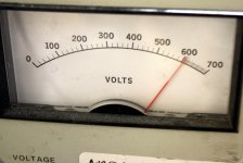
I changed a few resistor values, and now have a non-smoking board. To verify this, I switched on Kaptain Killowatt, and fed the board 650 volts, maximum output from the power supply. The board has been cranking out 400 volts P-P for about 2 hours. As set up the output swings from -50 volts to +350 volts. This is limited by the -80 and +350 volt supplies that feed the board....and the output mosfet.
I have swapped in 4 different types of tubes from the 21 possibilities. I tried a tube with a triode Mu of 18 and pentode Gm of 9000, as well as a tube with a triode Mu of 47 and pentode Gm of 23000. All work with minor trimpot adjustment.
There is too much gain, and the offset drifts as the board heats up, but these issues can wait until I melt some sweep tubes. I need to test out some local feedback ideas that will eat up some of the excess gain.
Attachments
Y'know another way to screen drive might be to hold the screen voltage
constant and swing the cathode and maybe G1 with a PNP or somesuch.
Or could perhaps hold both G1 and G2, to allow both grids drive...
constant and swing the cathode and maybe G1 with a PNP or somesuch.
Or could perhaps hold both G1 and G2, to allow both grids drive...
Heh, use Ken's PNP driver to drive the cathode of one output tube, and to also drive the screen of the 2nd output tube (may need an PNP/NPN totem-pole pair for this, and some DC offsets, or just float the DC screen supply on the drive). No phase splitter needed then. Even works for the conventional g1 drive case too.
Driving the cathode is interesting in that it also modulates the plate voltage supply some. Would make "screen" drive even more efficient, with a low plate voltage at idle.
Driving the cathode is interesting in that it also modulates the plate voltage supply some. Would make "screen" drive even more efficient, with a low plate voltage at idle.
Last edited:
Heh, use Ken's PNP driver to drive the cathode of one output tube, and to also drive the screen of the 2nd output tube (may need an PNP/NPN totem-pole pair for this, and some DC offsets, or just float the DC screen supply on the drive). No phase splitter needed then. Even works for the conventional g1 drive case too.
Driving the cathode is interesting in that it also modulates the plate voltage supply some. Would make "screen" drive even more efficient, with a low plate voltage at idle.
Cross couple both screens to the other driven cathode plus a DC offset...
Screen drive sometimes wants unreasonable voltage swings, cuts that
requirement in half...
Last edited:
- Home
- Amplifiers
- Tubes / Valves
- Show me your screen drive circuits