The IRF610 is only rated for 200 volts. I would use a 600 volt fet since you will run it on 300 volts or more and the screen will go to zero or below during cutoff. Voltage swings can be well over expected values when the amp is driven to clipping into an inductive load.
Assuming a class AB1, AB2, or class B amp:
You want NO sag??? Then you need an oversized regulated power supply capable of 667 mA per channel! This is the case when any tube capable of pulling the plate down near zero volts. Any sweep tube capable of 667+ mA of peak cathode current can do this. The typical audio tubes fall a bit short.
Where does the 667 mA come from? The per plate impedance of the OPT is 1/4 the plate to plate impedance, which is 825 ohms. The power supply is 550 volts, the tube is a near short. So zero sag needs a lot of current capability that uh, doesn't sag, which means regulation. Is this really needed? That can depend on your expectations, and the intended use of the amp. Do you want to play music, run test tones, or power a shaker table. Playing music, even use as a guitar amp, is the easiest of these cases.
Music has a "peak to average" ratio, also known as crest factor. This means that a 100 watt amp cranked where the peaks are clipped is putting out 1 to 10 watts average. Good quality recordings that are not heavily compressed are closer to, or below 1 watt! The crud that flows from a pop music radio station is heavily compressed to sound louder, and it is, the average power is closer to 10 watts. What does this mean.
Bob Carver has made a career exploiting this fact. It means that you can use a 10 watt power supply in a 100 watt amp to save costs. Put a big fat cap across the output to cover the peaks, and it won't blow up. I had one of his original M-400 400 watt amps. It had a 3 pound power transformer, and despite his warnings in the manual about using the amp for sound reinforcement, I played my guitar through it often and never blew it up! I drove 8 twelve inch speakers and played LOUD!
So, Is this really possible? Well, Carver ran his amps near class B and fixed the crossover distortion with GNFB. We could do this too, and screen drive will run near class B without excessive distortion. So, yes this is possible, and I am exploring the limits of tube amps squeezed into small spaces with minimized power supplies.
Recommendation? Unless you are SURE you are going to use screen drive, assume a typical idle current of 25 to 35 mA per output tube. This means 100 to 140 mA for 4 tubes, 200 to 280 for 8. This is consumed ALL THE TIME, and the power supply must deliver this without undue heating.
Assuming a minimalist design the power supply will need to supply only a bit more power for music demands. The amp is likely 50 to 75% efficient, so 10 watts of power requires 15 to 20 watts of additional power above the idle demands from the supply. Can you really do this? I have a Simple P-P running on a 100VA Antek toroid. The idle current plus heater current is 120 VA, and it has been running fine for 3 years. Yes there is a big fat cap (two actually) across the power supply and the bass is good.
Assuming a traditional textbook design we take the expected total output power, and factor in the efficiency, and build the power supply to feed the amp this much power all the time whether it needs it or not. So a 100 watt (50 WPC) amp that is 50% efficient, needs a 200 watt plate supply, plus screen, driver, and heater supplies. This is really needed if you want to test with continuous tones for long periods of time, or drive a shaker table! It isn't for most music.
Most amps built here fall in between these extremes. Where they fall is up to you. So back to SAG... A pentode amp is relatively immune to variations in plate supply voltage if the SCREEN and BIAS supplies are REGULATED! If you are using screen drive via a mosfet follower, the screen is controlled, and follows the drive voltage, so the driver supplied should be regulated.
So, sag isn't a big problem.....as long as the B+ voltage under full load conditions is sufficient to provide the desired power output. Obviously we don't want a supply that varies by 100 volts or more, so we desire a power supply with a low ESR....Effective Series Resistance. YES, the DC resistance of the power transformer and choke are a part of this, so the low DCR fanatics at least have some theory behind the insanity!
Full load might not be what you think it is. Remember the 825 ohms....That assumes an 8 ohm load.....8 ohm speakers are rarely 8 ohms, and only match that published curve under STATIC single tone conditions. When that woofer cone is moving in one direction and a bass drum hit tries to instantly drive it in the other direction the instantaneous impedance can drop well below 8 ohms. So a trend toward a bigger supply and a big fat cap isn't a bad idea either.....
So how do you size the power supply? I have never gone wrong (even in a guitar amp) with building the plate supply to deliver the idle current + 1/3 to 1/2 of the expected full power output. If the amp is less than 70% efficient, I may increase this a bit if it will be used for guitar or bass (even worse). Add the driver, screen and heater supplies. In a pentode amp, I regulate the screen and bias supplies, and let the plate supply sag.
 deicide67 - please be careful with the quite function. I have fixed you post #17.
Hi,
My apologies. Can you delete the repeat quote also? Sorry, it took me a moment to figure out what a "quite function" is. Kidding, and thank you🙂
My apologies. Can you delete the repeat quote also? Sorry, it took me a moment to figure out what a "quite function" is. Kidding, and thank you🙂
So how do you size the power supply?
since i design and build power traffos used in my tube amp builds, i go for maximum total power consumption at full power output plus some headroom...😀
I am looking at a few options. I have some big power iron to use for this amp. One I may have access to is a 640VCT @ 2A power transformer. So, ~425-450VDC B+ @ 2A.
I wish I could locate a choke that is big enough to use for a 2A choke input for ~575VDC, but I cannot locate anything like that. I would love it if someone could assist with finding one for that🙂
I wish I could locate a choke that is big enough to use for a 2A choke input for ~575VDC, but I cannot locate anything like that. I would love it if someone could assist with finding one for that🙂
OK,
I acquired two Hammond 1650T outputs. They are 1.9K A-A and rated for 120W. As Miles pointed out, the optimal load for a PP pair is around 2.54K. With a 1.9K output transformer, would I be better off using a pair or a quad of 6CB5A tubes into the load?
The outputs will handle around 400mA of current per side of the primary winding, so four tubes should not be a problem.
Thanks!
Blair
The 6CB5 has a peak cathode current rating of 850 mA. Depending on how many of those 120 watts do you want to use, how high it your B+, what you are going to play, and how loud you are going to play it, and how much of your speaker's impedance curve runs below nominal, I would lean toward 4 tubes per channel. They will have a far easier life if you intend to play loud music at loud volume levels.
If you really want to run two tubes per channel look for tubes with a higher peak current rating.
I have my new driver boards about 75% populated, and a breadboard that can use three different driver boards built. There will be some real screen drive tests coming soon. I will start a new thread for it all.
Very cool! I look forward to your tests.
I, also think four per channel is the way to go. I have a few options on B+. I'm leaning towards a higher B+ of 650-680V with a doubler. Or, I can run a 320-350V B+.
I am not going to run them at 75WRMS all day. More like 3-5W. My woofers just need power to properly drive them.
As for impedance, my speakers are almost a dead 4 ohm load until they get fairly deep in the octaves where they drop to around 2.5-3 ohms.
Blair
until they get fairly deep in the octaves where they drop to around 2.5-3 ohms.
If the impedance drop occurs in the range where there is some bass heavy music (30 to 80Hz depending on music) then 4 tubes will be the way to go. I don't have the space for the amp that I am planning or I would use 4 X 13GB5's per channel They are available for less than $1 each and I have seen well over 100 watts flow from 2 or them for like half an hour straight in G1 drive! They are really small for sweep tubes, but hard to melt. I have about 150 of them to "test."
I plan to do some experimenting with driving both G1 and G2 at the same time....but not necessarilly at the same levels, to see if I can avoid the "melted screen breakdown" region that occurs with high powered screen drive.
looking forward to it
I'd like to pre-subscribe to that thread 😀
Hopefully I can find some time to resurect my old screen driven PP EL36 experiment. Make for more flexibility this time to compare different sweeps, driver types, IT drive vs source followers...
Back then the bass was there, but not very controlled. Not much damping. Need to improve that as well.
There will be some real screen drive tests coming soon. I will start a new thread for it all.
I'd like to pre-subscribe to that thread 😀
Hopefully I can find some time to resurect my old screen driven PP EL36 experiment. Make for more flexibility this time to compare different sweeps, driver types, IT drive vs source followers...
Back then the bass was there, but not very controlled. Not much damping. Need to improve that as well.
I'd like to pre-subscribe to that thread
Sure.....once I decide on a name. As soon as the big switch on the 1KW power supply gets flipped, I will decide.....maybe next weekend..if it rains. Otherwise I got to put brakes in my car before bad stuff happens. I have been posting my experiments in whatever thread that seemed pertinent at the time. Looking back now it's nearly impossible for me to find my own experiments. I will post a link to the new thread in this one and the related high power sweep tube threads, and others.
Back then the bass was there, but not very controlled. Not much damping. Need to improve that as well.
I noticed the same in some of my early screen drive experiments. I have applied local feedback around the output tube to improve things.
Do you think I would do better off the lower B+ or the higher?
I'm fine doing it either way. I've decided to eliminate the choke on the B+ in case I go pentode and current demand exceeds 500mA for the 4 power tubes.
What kind of voltage swing is needed to drive 4 of these in PPP?
Thanks!
I'm fine doing it either way. I've decided to eliminate the choke on the B+ in case I go pentode and current demand exceeds 500mA for the 4 power tubes.
What kind of voltage swing is needed to drive 4 of these in PPP?
Thanks!
Last edited:
Hi George,
You said that any FET with a Crss of 50+V will work, but most datasheet a I find have that rating in Pf vs. volts as a capacitance rating. There is a voltage rating beside that as Vds. Is that the voltage I'm looking for?
Will the tube compliment you are using there drive a quad of 6CB5s?
Thanks!
You said that any FET with a Crss of 50+V will work, but most datasheet a I find have that rating in Pf vs. volts as a capacitance rating. There is a voltage rating beside that as Vds. Is that the voltage I'm looking for?
Will the tube compliment you are using there drive a quad of 6CB5s?
Thanks!
There is a curve in the data sheet that shows Crss VS voltage. Look for a part that is flat out beyond 50 volts. The number should be around 10pf or less. I have 3 different driver boards to ttry. One uses 6sn7. One uses any tube with the 9dx base.one ie Peres board.
Thanks George! I see the curves now at the end of the sheets. Digging around a little, I found this:
http://www.diyaudio.com/forums/atta...pus-5-0-modern-mullard-visio-ab2schema_v5.pdf
Looks pretty nice. Just so I understand, the -90V B- rail only needs to be 20-30mA? I assume the 500K pots are to adjust the output tube bias current?
If it were to be done in PPP, would it require four MOSFET source followers to independently adjust the bias points like I do on my PPP UL amps?
Thanks!
Blair
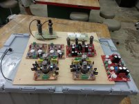
I was typing my last post while sitting in my car waiting for my weekly wood shop class, so I messed up some of the typing. I get 3 hours away from the real world a week to play with tools that can cut body parts off......quickly. Tonight I made a 4 X 8 sheet of plywood into the components for 3 speaker cabinets, and two amp heads, all guitar amp stuff.
I also had my latest bread board with me because I was going to make heat sink brackets for the mosfets if I couldn't get the table saw, but I got there first! I set the breadboard on the work table and took a phone camera picture. This is what I will be using for all amp experiments in the near future. It is simply a piece of plywood with holes drilled to mount a pair of driver boards (there are 3 sets to choose from), a pair of output boards and a pair of OPT's. All power comes from bench power supplies. The output boards are turret boards from AES, the octal board will also fit Novar (shown with 13GB5's) and 12 pin compactron sockets. I have a set for nine pin Noval (EL84) tubes.
You will see a pair of red boards, these are Petes P-P driver boards. Excellent driver boards, but no mosfets for screen drive:
http://www.diyaudio.com/forums/tube...push-pull-driver-pcb.html?highlight=6l6gc+ab2
There is a pair of boards with two octal tubes on each board. They are currently mounted in the driver seat. These boards were designed for during this thread and the entire design was laid out for all to see and follow along. The schematic can be found in that thread, Screen drive and sweep tubes were not the focus of this design, but it can handle it just fine. I think I had to make a minor change in the mosfet circuit
http://www.diyaudio.com/forums/tubes-valves/133034-6l6gc-ab2-amp.html?highlight=6l6gc+ab2
There are also a pair of unfinished boards with two 9 pin sockets each. They can use any tube with a 9DX base connection. These are triode pentode pairs. There is about 20 different type numbers with identical pinouts. I intend to test them all.
Attachments
Well now, that 6l6 thread will take a few minutes to read through. Pete needs no introduction for me. He's the wild man with the Hawaiian shirt that lives down the street from me.
His red board is fairly large, hence the "Big red board" title🙂 he has another board with just the driver topology on it that is much smaller.
I am not opposed to point to point wiring, and have not found anything for screen drive which is what I want to try. I think I am going to try a lower B+ for initial testing, and go from there. The 2SK2700 looks like a decent candidate for your schematic that was posted in the first page of this thread. I am planning to tinker around with the driver tube. For some reason I'm pretty bent on the 6GF7A as the driver tube.
Also contemplating a transformer based phase inverter because I've never done it either.
Do you have a link? I'm not oppose to pentode at all. I've just never done screen drive🙂
have fun...High Gm driver pentodes
pentodes can be run triode for greater voltage swings into screen grid drive...
i still will use a mosfet source followers to drive the grids directly....
- Home
- Amplifiers
- Tubes / Valves
- Show me your screen drive circuits