Thanks for checking your group, Mark.
I re-checked my J175s at 15V, with zero added resistance on source or drain, just an inline ammeter (I figured out what I was doing wrong before). Instantaneous readings (less than one second after power-on) gave:
26+ to 29mA: 6 devices
26-25mA: 6 devices
23-24mA: 8 devices
It does look like I got a somewhat low Idss batch. I'm going to use the 26-29mA group for Hornet.
Kitty Hawk
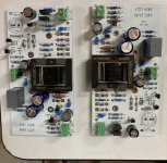
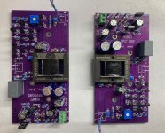
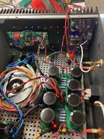
I finished building a pair of Kitty Hawk boards yesterday & swapped them in my Ship this day.
Part subs & build details: For R6, I didn't have 4k3R resistors due to an order or picking error, so I used 4k7R instead, based on a napkin calculation that the first regulator would drop ~6V with a 4k7R instead of ~8.2V with the 4k3R. The second and final regulator is now probably dropping ~8.4V, which is within the max 32V in-to-out drop spec of the LM317L. Assuming I understood the regulator setpoint equation & can do basic math, that is.
I couldn't source ZTX957s from any of the usual suspects so I looked around for substitutes and landed on onsemi's SS8550DBU, a high current PNP transistor. It's a much, much lower voltage part than the ZTX957, 25V vs 300V, but Kitty Hawk's regulator should output 19.7V (again if I understood the equation), which is less than the 25V rating of this piece, plus there's resistors in between the regulator and the emitters, so okay maybe.
As for the magic J_TH1, I'm using J113's with Idss between 8.7 and 9.2mA. I have extra!
I'm still using a First Watt style single rail linear power supply for now, but I removed the speaker delay board as it didn't seem to help much with the turn-on kick. The OS's pull a stable 1.7A with a 35.5V rail, and things do get hot.
As for the sound? I test my amps on 4" full range speakers, driven with an ACP+ from an Airplay digital source, and it was immediately obvious how thrusty and deep the bass was now, compared to Pequod. Kitty Hawk gives this amp real cojones. Also, there's noticeable reverb, and room echo, and breath to the music which is striking. It sounded so amazing I couldn't wait to move it into my main system, where an Iron Pre is feeding it and it's driving 2-ways, still with the same digital source for now. Kitty Hawk is really amazing, night and day compared to the delicacy and softness of Pequod.
Attachments

Congratulations, @ranshdow !! Good on ya. Kitty Hawk is a hell of a race car; I'm delighted it pleases you.
The Rush cascode asymmetric input stage used in KH, happens to be a great match to Theseus's single ended power supply. Perhaps one reason why you don't often see Rush cascodes, is that you don't often see single ended power supplies (?).
The Edcor 1:5 output transformer means we don't have to swing much voltage on the primary to get LOTS of voltage swing on the secondary. Thus KH runs quite nicely on a sub-20-volt, extremely regulated supply. Providing scads of PSRR, channel separation, and isolation from output stage supply noise.
_
Attachments
@Mark Johnson
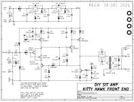
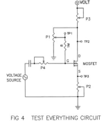
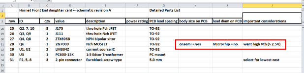
I have a question for you regarding Hornet. Q6, the 2N7000 MOSFET, is specified on the schematic as requiring devices with a threshold voltage > 2.5V. Nelson Pass's Practical Mosfet Testing for Audio states that Vth is defined for a given current, and gives the circuit in Fig 4 below as a way to test for Vth among other things. I can't tell what current Q6 will pass in circuit, but I see an 180R resistor on it's source. If that's the right idea, what circuit and voltage should I use to test candidate devices for Vth at the appropriate current for Hornet, and where is Vth measured? Sorry, I'm really kind of lost on this one.
I have a question for you regarding Hornet. Q6, the 2N7000 MOSFET, is specified on the schematic as requiring devices with a threshold voltage > 2.5V. Nelson Pass's Practical Mosfet Testing for Audio states that Vth is defined for a given current, and gives the circuit in Fig 4 below as a way to test for Vth among other things. I can't tell what current Q6 will pass in circuit, but I see an 180R resistor on it's source. If that's the right idea, what circuit and voltage should I use to test candidate devices for Vth at the appropriate current for Hornet, and where is Vth measured? Sorry, I'm really kind of lost on this one.
Attachments
Get a big pile of MOSFETs because you are going to destroy a few while debugging your apparatus.
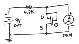
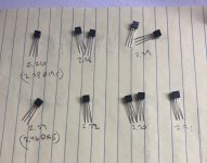
Connect a 9V transistor radio battery, a 4.7K resistor, and your DC voltmeter, as shown below. Connect MOSFET candidate #1 as shown below. Read the DC voltage. Write the measured voltage on a piece of paper and tape that MOSFET to the paper right next to the written voltage.
Connect MOSFET candidate #2 as shown below and read the DC voltage. Write the voltage on the paper and tape MOSFET #2 to the paper next to its measured voltage.
Do this for about 10 MOSFETs. If some of them have voltage measurements exceeding 2.5 volts, pick the highest. If none of them have voltage measurements exceeding 2.5 volts, you either did the measurements incorrectly or you bought from the wrong fab. Try a few more, double check your hookup, hope for success.
Every 15 minutes or so, check the 9V battery voltage. This test will discharge the battery and if that happens, you want to know about it.
If you don't have a 4.7K resistor, connect two 10K resistors in parallel.
If you don't have either 4.7K or 10K, connect five 1K resistors in series.
Attachments
Thanks, Mark.
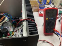
So 10 onsemi 2N7000 MOSFETs from Farnell, purchased back in January, gave me a Vth range from 2.26V to 2.34V in your test circuit. Interestingly, when tested with my cheap transistor tester, which I don't trust, they were in two buckets of 2.4V and 2.5V. I also thought to test them at 19.5V, because that's the voltage the Drains would see at VTOP (I built and read the power supplies of two Hornet boards and the lower of the two gives 19.4V from 36V in). The range at 19.5V wasn't much higher, 2.38V to 2.46V. Guess I need to order some more.
So 10 onsemi 2N7000 MOSFETs from Farnell, purchased back in January, gave me a Vth range from 2.26V to 2.34V in your test circuit. Interestingly, when tested with my cheap transistor tester, which I don't trust, they were in two buckets of 2.4V and 2.5V. I also thought to test them at 19.5V, because that's the voltage the Drains would see at VTOP (I built and read the power supplies of two Hornet boards and the lower of the two gives 19.4V from 36V in). The range at 19.5V wasn't much higher, 2.38V to 2.46V. Guess I need to order some more.
Attachments
The ones you correctly avoided, from Microchip, will read out "0.5V" on this test protocol and that's NOT what you want. If I were you I'd pick the two largest of the whole bunch and cross my fingers that it's all going to be okay.
Hornet
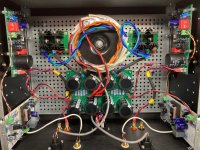
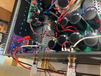
Got these up & running today. Garage listening impressions on a very hot day (with a fan and washing machine running, and other doings) is of smoothness and detail, noticeably in the midbass. Eventually this amp will be heard in my main system.
Some build details: I used J111's of Idss ~85mA, J175's of Idss 26-29mA, and 2N7000s of Vth just under 2.5V. Also ZTX696B were nearly impossible to source back in January so I substituted 2N5551s, which was a digi-key suggestion. The ZTX696B is an NPN with a 500mA collector current and 5V emitter to base voltage, the 2N5551 has a 600mA collector current and 6V emitter to base voltage. The 2N5551 has a lower range of current gain than the ZTX696B. At the operating point of their respective circuits, ~10mA if I did the LM334 regulator math right, they might be similar enough. I don't know.
Anyway it was no problem to adjust the RV1 pot to give 25mA (480mV) across the 20R resistor R17. I noticed this value would be high upon startup, take a good minute to settle within range, and would creep lower as the amp got hot. I checked it a couple of times and tweaked it a bit after an hour of listening.
Attachments

Hi.
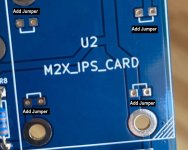
A question regarding the Nimitz daughter board (mine in blue). The small "U" line are to weld a wire ( seen on the pictures in the 1st post related to "Ship of Theseus", Nimitiz board in black, red circles added by me)?
Reason for those wires is the same as in the M2x build? extract from the manual "
2. Jumpers. When you look at the amplifier main board, you’ll see four white U‐
shaped markings inside the rectangle where the input stage module is bolted.
Look for the text “I/O 1” , “I/O 2” , “I/O 3” , “I/O 4”. The U‐shaped markings are
less than 1cm from those pieces of text. Just bend some scrap AWG22 wire into a
U shape (resistor cut‐off leads are perfectly fine too), stuff into the component
side, add a piece of masking tape to hold it in place while soldering, and solder
both ends on the back. Trim flush, remove tape, done. The purpose of these
jumpers is to provide a safety backup, and a backup‐to‐the‐backup, guaranteeing
that the bolts are electrically connected to both sides of the amplifier main board.
Even if the plated‐through‐holes somehow become no_longer_plated on this
board. Yes we are preparing for a very unlikely tornado‐during‐earthquake event.
But the cost of preparation is zero, so: why not?" ?
Just would like to check if my understanding is correct...
Yes within the rectangle labeled "U2 M2X_IPS_CARD" there are indeed four pairs of drill holes, where each pair has a "U" shaped line on the white top-silkscreen layer. Yes the intention is that you install four jumper wires, one for each pair of holes marked with a "U".
This is a highly redundant safety measure, whose only purpose is to provide a second and third current pathway, in order to short together the annular rings on top and bottom copper layer. It protects against a situation where the plated-thru-hole metal eventually gets rubbed away. With these jumpers, we now have even more confidence that the hex nut and star washer which touch the bottom copper layer, are connected (redundantly) to the hex nut and star washer which touch the top copper layer. And this is true even if some metal has been rubbed away.
_
Attachments
Hi
Regarding the “Ship of Theseus”, I would really like to have a 3U 300mm chassis, so it could fit into standard furniture, with some room to spare for ventilation.
I would like to know if it could be OK given the thermal dissipation?
Asking the question to the forum, I also did the following as “homework”:
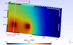
Since I wasn’t sure of the “Ship of Theseus” power dissipated through the Mosfets , I roughly modelled a 4U 300mm heatsink, with the disposition of the Mosfets as seen on a few builds (power channel on 1 side of the heatsink, input board on the other side), put the Mosfet T°C @75°C (metallic skin temp), put some convection inside and outside as reference. Calculation is done with a mechanical software akin Abaqus, with rough hypothesis and basic thermal solver, not a dedicated thermal software. Nothing changes except position/number of Mosfets, height of heatsinks. This is just to get going / see the big picture. Hence ”Reference-Theseus-4U-Builds” picture
Then:
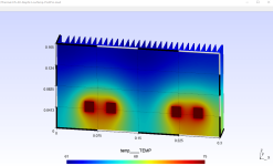
1. 4U 300mm heatsink, moving the Mosfets to the center, how does the temperature change? “Theseus-4U-Mosfets-Centered” picture
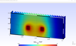
2. 3U 300mm heatsink, Mosfets positionned to the center, how does the temperature change? “Theseus-3U-Mosfets-Centered”
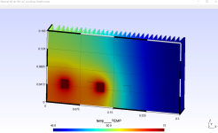
3. (since it didn’t go really in the direction I hoped for, I went to compare to a 4 Mosfets amp, the AlephJ, with its Mosfets arrangement) 4U 300 heatsink, Mosfets per Aleph config. “AlephJ-4U-Builds” picture
Prior to the analysis/reflexion, “Tmax-Vertical-High-Low” picture explain what I mean by “Tmax @vertical mosfet high & low”. This the max temp. at the vertical of 1 mosfet, either on Top or at the bottom of the heatsink.
Here is the table regarding temperatures estimated (“CAE based rules of thumbs”)
Hence my reflexions:
A. Tmin for “To Build?” 3U 300mm Centered Mosfet is lower than AlephJ in 4U 300mm (config working for several people already)
B. Tmax vertical high/low is inferior to Tmax Vertical Low from the “Reference Theseus 4U” when the 2 mosfets are positionned on the extrem left side (picture of successful builds in this thread)
So, from A & B, I would believe, using AlephJ configs & “Ship Of Theseus” “power channel on the left side”, it should be OK to have a Ship of Theseus with 3U 300mm heatsinks, with power channel / mosfet centered.
=> Would you agree ? Or is there something I missed?
Regarding the “Ship of Theseus”, I would really like to have a 3U 300mm chassis, so it could fit into standard furniture, with some room to spare for ventilation.
I would like to know if it could be OK given the thermal dissipation?
Asking the question to the forum, I also did the following as “homework”:
Since I wasn’t sure of the “Ship of Theseus” power dissipated through the Mosfets , I roughly modelled a 4U 300mm heatsink, with the disposition of the Mosfets as seen on a few builds (power channel on 1 side of the heatsink, input board on the other side), put the Mosfet T°C @75°C (metallic skin temp), put some convection inside and outside as reference. Calculation is done with a mechanical software akin Abaqus, with rough hypothesis and basic thermal solver, not a dedicated thermal software. Nothing changes except position/number of Mosfets, height of heatsinks. This is just to get going / see the big picture. Hence ”Reference-Theseus-4U-Builds” picture
Then:
1. 4U 300mm heatsink, moving the Mosfets to the center, how does the temperature change? “Theseus-4U-Mosfets-Centered” picture
2. 3U 300mm heatsink, Mosfets positionned to the center, how does the temperature change? “Theseus-3U-Mosfets-Centered”
3. (since it didn’t go really in the direction I hoped for, I went to compare to a 4 Mosfets amp, the AlephJ, with its Mosfets arrangement) 4U 300 heatsink, Mosfets per Aleph config. “AlephJ-4U-Builds” picture
Prior to the analysis/reflexion, “Tmax-Vertical-High-Low” picture explain what I mean by “Tmax @vertical mosfet high & low”. This the max temp. at the vertical of 1 mosfet, either on Top or at the bottom of the heatsink.
Here is the table regarding temperatures estimated (“CAE based rules of thumbs”)
Setup | Tmax | Tmin | Tmax Vertical (High) | Tmax Vertical (Low) |
Reference Theseus 4U (most builds) | 75 | 46.8 | 61.2 | 69.2 |
Theseus 4U Mosfets@Center | 75 | 52.9 | 59 | 67.1 |
Theseus 3U Mosfets@Center (to build?) | 75 | 55.6 | 65.4 | 68.2 |
AlephJ 4U | 75 | 61 | 61.6 | 66.2 |
Hence my reflexions:
A. Tmin for “To Build?” 3U 300mm Centered Mosfet is lower than AlephJ in 4U 300mm (config working for several people already)
B. Tmax vertical high/low is inferior to Tmax Vertical Low from the “Reference Theseus 4U” when the 2 mosfets are positionned on the extrem left side (picture of successful builds in this thread)
So, from A & B, I would believe, using AlephJ configs & “Ship Of Theseus” “power channel on the left side”, it should be OK to have a Ship of Theseus with 3U 300mm heatsinks, with power channel / mosfet centered.
=> Would you agree ? Or is there something I missed?
Attachments

Your simulations look good.
The real question is are you willing to use a fan if the 3U/300 is insufficient for the desired temperature?
The thermal load is about 60W per channel. What thermal efficiency are you using to model the heatsink?
The real question is are you willing to use a fan if the 3U/300 is insufficient for the desired temperature?
The thermal load is about 60W per channel. What thermal efficiency are you using to model the heatsink?
Theseus Amp Channel uses the same Constant Current Source as Nelson Pass's Lottery Pchannel VFET amp. According to Nelson's writeup (link), this CCS delivers a constant 1.6 amperes. So the power dissipated per channel is (1.6A * 36V) = 57.6 watts. It is a very good approximation to assume that the power dissipation is ~~ evenly divided between the two output transistors. Each transistor thus dissipates 28.8 watts. In easy-to-remember round numbers: 30 watts per transistor ---> 60 watts per channel.
Last edited:
Hi.
@6L6
A. I am not using a specific thermal efficiency for the heatsink: just the dimensions of the HS (obtained from ModuloShop/Hifi2000 through a separate discussion) & the material = aluminium, with its density & thermal properties. The fins are straight (Vs ondulated for the original HS) but the goal is to have roughly the right mass of aluminium, numbers and dimensions of the fins, type of material. [Thermal efficiency is, i believe, a consequence of those parameters)
A bis. I went "CAE" because just using global thermal efficiency for the whole heatsink whereas i could see builds of the "Ship of Theseus" putting only 1 side to use was a bit of a waste and...really would like a 3U chassis.
Yet i discovered the height contributes to decrease the temp a lot more than i would have thought!
B. I could put a fan but i am willing 1st to buy cheap 2nd hand heatsink for prototyping (and comparative calculation) before making a final decision on the chassis HS
For instance, I have searched for dual voltages SMPS (36V + 5/12/24 or else voltage for the fan, not that many...).
But i would prefer not having to use a fan.
Hence the comparison with 2 "references" (Theseus built by others with the "left side mounting", AlephJ)
C. Steps files of the approximated HS attached for reference.
@Mark Johnson
A. Thanks. I knew i could go with the electric current going through the device, but i dreaded a bit that approach. You made a good worst case scenario, reminding me of the voltage & current going through the device
60W for 4U-300mm is 0.31*60=18.6degrees for 1 channel (HS thermal specs)
60W for 3U-300mm is 0.4*60=24degrees for 1 channel
(...global approach...)
B. Electric current, MOSFET specs and Internet tutorials should also lead to a better approximation of the temperature @mosfet location on the Heatsink= that's what i dreaded! it is another approach worth investigating for the different amps.
C. I have an M2X 4U 400mm, electric behavior & thermal assessment could provide some infos in the long run or more quickly if i can get a skin temperature sensor... / use it as another reference for calculation...
Thank you both for providing some pointers, i will investiguate more when i have the time.
Cheers
Attachments
I have an Aleph 20 with an estimated thermal disspation of 66W/ch that is in a 3U/300 chassis. There are four MOSFETs per side so four point sources of heat. On warm evenings after running for an hour or so I can't hold my hand to the heat sinks or face plate for more than a second. It's a judgement call whether one considers this okay.
My Ship of Theseus is in a 4U/300 Deluxe chassis, where I'm using it with a linear power supply. The rectifiers and the power supply resistors dissipate heat beyond what the FE and OS dissipate. On warm evenings it too gets quite hot to the touch but subjectively not as hot as the Aleph in the 3U/300. This is anecdotal.
Edit: One thing to add, though. If you intend to mount the FE cards on heat sinks drilled with the UMS pattern, they won't fit on a 3U height heat sink, regardless of length. They only just fit vertically on a 4U heat sink. The picture below is one of the FE cards mounted in a 4U/300 Deluxe. If you go 3U/300, you'll have to get clever mounting the FE cards, and almost certainly will need an SMPS, likely an outboard brick type.
Attachments

Last edited:
Good anecdotal reference, @ranshdow. I have some different class A builds in 3U300 and 4U300 and your description aligns with my experience. Some builds I feel much better with some fans blowing on the heatsinks, others I prefer to let loose. All depending on the ambient temperature.
It seems there is a delineation between sinks at <55*C and those >55*C. It depends on the F in FAB.
It seems there is a delineation between sinks at <55*C and those >55*C. It depends on the F in FAB.
Also. This got me wondering about the floor space in a 3U/300. If one tried to use an internal SMPS, one would need to mount either the power filter board or the SMPS vertically somewhere, maybe against the inside of the face plate. In which case, I'd absolutely ask and pay Gianluca to tap and drill blind threads in the inside of the face plate for you, in the layout you need. There isn't enough room for them all to lay flat.
Attachments
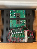
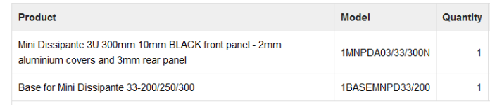
Is that Mini Dissipante? That’s my favorite chassis format from Gianluca.
FYI, external power supply frees up a lot of real estate.
FYI, external power supply frees up a lot of real estate.
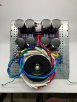
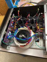
Yes, it's a Mini Dissipante. I'd also recommend the base plate, it just makes mounting and assembly much more pleasant, especially if you're nuts like I am and try to stuff a donut in a 3U/300.
Attachments
- Home
- Amplifiers
- Pass Labs
- Ship Of Theseus: compatible, interchangeable amplifier modules