A cap multiplier would be a perfectly good way to throw a way a couple of volts. And it’s easy to implement.
EDIT: A good place to start is Zen Variations 3. https://www.passdiy.com/project/amplifiers/zen-variations-3
EDIT: A good place to start is Zen Variations 3. https://www.passdiy.com/project/amplifiers/zen-variations-3
Last edited:
All the Antek spec sheets I've read show load testing at 120VAC. Example attached. I may have missed many, many of them though. What's confusing is that they show in their little blurbs... that "They are specially designed to work on all standard 115V or 230V."Measure the the actual secondary voltage. Anteks are rated for 115V mains, my mains run 123V -125V so the secondary winding real measured voltage is always higher than the spec sheets.
YMMV, but my takeaway is... I always check the specs for each model and definitely across manufacturers. With no load, and at 120VAC, the transformer in the spec attached should measure 28.5VAC.
I've found their specs to be spot on with the 4 or 5 variants I've used. With that said, I've never run one up to the load in their specs that reaches the "2nd level". I also wish they'd put the load in the spec that results in the expected secondary voltage at 120VAC input... but... usually it's close enough for me. Maybe there is some set of rules or standardization around it that I haven't found yet...
Edited to add, and a bit OT, but you can plug values into PSUD for transformer regulation... it works pretty well. 🙂
Attachments
Back to this. With 120.4VAC measured on the mains between line and neutral, my example of the AS-3428 gives me 29.46VAC and 29.48VAC for the two secondaries, respectively. This is while the secondaries, are connected to bridge rectifiers and the rest of the CRC block, but otherwise unloaded. I didn't measure these with my light bulb DC load. On the DC side as mentioned I'm getting 39.58 to 39.61VDC, or 1.34:1. So the trafo seems to be more or less in spec, maybe a volt high on the secondaries. I still like the cap mx idea.
So to make a long story short and with thanks to @6L6 , I designed and implemented a simple cap multiplier following Papa's worked example in Zen variations 3. Unloaded, the rails after the cap mx are 35.4V, compared to ~39V before the cap mx, so an ~4.5V drop, great. With the OS and FE stages connected, however, the rails after the cap mx dropped to ~31.8V, and the rails before the cap mx are now ~36.5V. I'm surprised by this much voltage sag from a CRC supply fed by a 300VAC donut, but it is what it is. This implies that just loading the CRC directly with the Ship of Theseus, no cap mx, should be enough to drop the rails to an acceptable range. Haven't done that yet, but it's likely the next step.
Attachments
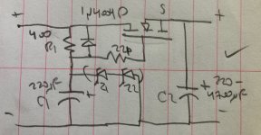
39.1V of Zener, which should drop 39.6V of unloaded supply to 35.1V, assuming there's 0.5V of drop across that first resistor. 2mA with a 0.5V drop works out to 250 Ohms. I used 410 Ohms, which was a design error but I went with it anyway. Maybe the Zeners weren't conducting.
My Ship is a now a Motorboat
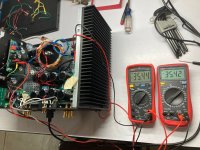
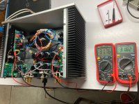
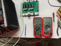
Okay, pulled the cap multipliers & hooked the OS and FE boards directly to the linear power supply. There's an 0R1 current sense resistor in the negative leg to the OS boards, a leftover in the hook-up wires I had laying around from a previous project, because I was curious about the current draw with this supply. The loaded rail voltage is 36.3V and there's 0.17V dropped across the current sense resistor, so 1.7A bias. Note, switching voltmeters gives a different answer, of 1.6A, so anyway. Dialing the source bias to half of rail, 18.16V, was no problem.
There is minor hum at the speakers now, compared to the SMPS supply. It doesn't vary with volume and I do have to have my ear right up against a driver to hear it. The turn-on speaker kick also seems more severe but granted my testing today was done with sensitive 4" full range drivers, so they're easy to kick. I had one of the speaker protection circuits that the diyaudiostore sells, so I put that in, powered off of one of the unused 15VAC secondaries. Interestingly, powering that circuit dropped the other rails to 35.9V, so I dialed the source biases back to 17.9V. It does the turn-on delay but there is still a kick when the relays latch the speakers into the circuit. Also I think the hum is worse with the protection relay than without.
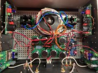
It took about an hour in the garage for this amp and speaker combination to mellow and bloom, but it did, and it's promising enough that I'll put this amp in my main system soon for some extended listening. But it least it works, and thus a First Watt F1 style linear supply can be adapted to power a Ship of Theseus, albeit with some hum. I'd recommend this experiment to those considering building outboard linear PSUs for other laptop-brick powered amps before going full-send into those builds.
Okay, pulled the cap multipliers & hooked the OS and FE boards directly to the linear power supply. There's an 0R1 current sense resistor in the negative leg to the OS boards, a leftover in the hook-up wires I had laying around from a previous project, because I was curious about the current draw with this supply. The loaded rail voltage is 36.3V and there's 0.17V dropped across the current sense resistor, so 1.7A bias. Note, switching voltmeters gives a different answer, of 1.6A, so anyway. Dialing the source bias to half of rail, 18.16V, was no problem.
There is minor hum at the speakers now, compared to the SMPS supply. It doesn't vary with volume and I do have to have my ear right up against a driver to hear it. The turn-on speaker kick also seems more severe but granted my testing today was done with sensitive 4" full range drivers, so they're easy to kick. I had one of the speaker protection circuits that the diyaudiostore sells, so I put that in, powered off of one of the unused 15VAC secondaries. Interestingly, powering that circuit dropped the other rails to 35.9V, so I dialed the source biases back to 17.9V. It does the turn-on delay but there is still a kick when the relays latch the speakers into the circuit. Also I think the hum is worse with the protection relay than without.
It took about an hour in the garage for this amp and speaker combination to mellow and bloom, but it did, and it's promising enough that I'll put this amp in my main system soon for some extended listening. But it least it works, and thus a First Watt F1 style linear supply can be adapted to power a Ship of Theseus, albeit with some hum. I'd recommend this experiment to those considering building outboard linear PSUs for other laptop-brick powered amps before going full-send into those builds.
Attachments

The schematic in post #304 looks more like a voltage follower regulator than a capacitance multiplier.
If the zener string of Z1 and Z2 is 39.1V, the input voltage needs to be higher than 39.1 before the regulator works. The output voltage will be the zener string voltage minus the mosfet Vgs. If the unloaded input voltage is 39.6V, that is too close to the zener string voltage. Zeners also have tolerances so their voltage drop needs to be measured in circuit to determine their exact voltage. Also taking into consideration that the linear power supply may have voltage sag under load, and also have voltage variation from line voltage variation, the zener voltage is too high.
If the linear supply under load sags to 36.3V from 39.1V unloaded, then regulator will not function with 39.1V of zeners. The zener voltage would need to be less than 36.3V.
Last edited:
I tried clipping out the Zener string to see what if anything would happen to the output voltage of the cap multiplier. There was a very slight change in output voltage, I think lower, but I didn't record the observation.
What do you mean by "clipping out the Zener string"? Did you disconnect the Zeners from the circuit?
As I mentioned earlier, your schematic does not show a capacitance multiplier. If you remove the zener string then it is a capacitance multiplier.
The voltage output will be lower than the input voltage by the value of the mosfet Vgs. The output voltage will track with the input voltage.
By the way, from what I have seen of capacitance multiplier schematics, the value of the resistor is usually much higher than 400 Ohms. 400 Ohms works for the voltage follower regulator as it provides voltage drop for the zener string, but may not be optimal for a capacitance multiplier. For the capacitance multiplier, the resistor is in series with the mosfet gate, and because the mosfet gate current is very low, the resistor does not drop much voltage. For instance, Juma's Easy-Peasy Capacitance Multiplier has a 10k resistor. The resistor combined with the capacitor form a RC filter to reduce the ripple in the gate voltage.
Juma's Easy-Peasy Capacitance Multiplier
You need to decide whether you want a regulated supply or a capacitance multiplier supply. Either way, the output voltage will be lower than the loaded input voltage.
Last edited:
Hi Ben,
I was following the attached circuit in my design, from Nelson's Zen Variations 3. It is described as a "voltage follower regulator", so your terminology is correct. As described in the article, C1 will respond to ripple on the unregulated supply, and drive the gate accordingly. My interpretation is thus that this circuit 'multiplies' the capacitance of C1, but with a ceiling and a floor on the gate voltage: the ceiling being (V+ unreg) - forward voltage drop of the shunt diode, the floor being the reverse voltage of the Zener string. My understanding is that the Zener voltage floor was the basis for the regulation of the output, when the circuit is designed to ensure that Zener string is conducting to ground. Clipping or removing the Zener string removed the voltage floor, hence the regulation, hence turning it into a basic cap multiplier, as I understand it.

Anyway my design goal here wasn't really a regulated supply, nor a ripple filtered one, but a simple way to drop about 4V at high current from an existing unregulated linear CRC supply. The voltage floor provided by the Zener string, properly designed and implemented, seemed like a nice bonus, but there wasn't enough voltage headroom for me to implement it properly, and as mentioned in an earlier post, I made an error in my calculations vs. that implementation. Also as stated above, putting the OS in circuit loaded down that unregulated supply sufficiently that this voltage dropping function became unnecessary, so I'm no longer using this cap multiplier at all.
I appreciate your feedback and guidance Ben, both here and in past conversations. I am still actively learning.
I was following the attached circuit in my design, from Nelson's Zen Variations 3. It is described as a "voltage follower regulator", so your terminology is correct. As described in the article, C1 will respond to ripple on the unregulated supply, and drive the gate accordingly. My interpretation is thus that this circuit 'multiplies' the capacitance of C1, but with a ceiling and a floor on the gate voltage: the ceiling being (V+ unreg) - forward voltage drop of the shunt diode, the floor being the reverse voltage of the Zener string. My understanding is that the Zener voltage floor was the basis for the regulation of the output, when the circuit is designed to ensure that Zener string is conducting to ground. Clipping or removing the Zener string removed the voltage floor, hence the regulation, hence turning it into a basic cap multiplier, as I understand it.
Anyway my design goal here wasn't really a regulated supply, nor a ripple filtered one, but a simple way to drop about 4V at high current from an existing unregulated linear CRC supply. The voltage floor provided by the Zener string, properly designed and implemented, seemed like a nice bonus, but there wasn't enough voltage headroom for me to implement it properly, and as mentioned in an earlier post, I made an error in my calculations vs. that implementation. Also as stated above, putting the OS in circuit loaded down that unregulated supply sufficiently that this voltage dropping function became unnecessary, so I'm no longer using this cap multiplier at all.
I appreciate your feedback and guidance Ben, both here and in past conversations. I am still actively learning.
Last edited:
Yes, the zener string and resistor is a shunt regulator which provides the gate voltage to the mosfet voltage follower. So the circuit is a voltage regulator. The output voltage remains constant as long as the input voltage is higher than the regulated voltage.
The capacitor mulitiplier on the other hand does not have the zener/resistor shunt at the mosfet gate. It has a resistor-capacitor (RC) filter that reduces the ripple in the gate voltage to the mosfet voltage follower. The output voltage is not constant but tracks the input voltage, but the output ripple is lower than the input ripple because of the RC filter at the mosfet gate. Perhaps a more appropriate name for it would be voltage follower RC filter.
The capacitor mulitiplier on the other hand does not have the zener/resistor shunt at the mosfet gate. It has a resistor-capacitor (RC) filter that reduces the ripple in the gate voltage to the mosfet voltage follower. The output voltage is not constant but tracks the input voltage, but the output ripple is lower than the input ripple because of the RC filter at the mosfet gate. Perhaps a more appropriate name for it would be voltage follower RC filter.
The direction I'm heading these days with power for the line level stuff is: zener referenced series reg -> RC filter -> and a "fast" cap multiplier (and some decoupling) right at the load... Each phase of each channel getting this 3 stage combo. Goal is just to maximize the pro's and minimize the con's of each element in a simple, reliable, and very effective way.
Be sure to plot the Line Rejection (deltaVout / deltaVin) from 1 Hz to 10 MHz. Methinks you'll discover that cap multipliers are pretty weak in some frequency bands. It's "AC analysis" in spice-style simulators.
Hi
I was searching within this thread but couldn't find: regarding power & distortion, should the "Ship of Theseus" be considered similar to the Sony DIY VFET amp (described in pdf, link @start of the thread) or is it different ? (different enough that somebody having both would have compared them?)
Thanks in advance and have a nice day
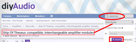
I can't recall whether I've seen such measurements in this thread or not, sorry. You might get some quick answers by trying searches within this one particular diyAudio thread. Examples below; I'm confident you can think of many more. For example REW , Quant Asylum , Spectrum , and of course: Measurements . Good luck!!
_
_
Attachments


No luck!
Before posting, i did the search with "power", "distortion".
Then your suggestion.
What is a good direction is this post https://www.diyaudio.com/community/...ngeable-amplifier-modules.383745/post-7337758 but that's all.
Anyways, the Venn diagram of "have Sony DIY VFet", "have Ship of Theseus", "have done the power/distortion/freq. response" measurements & comparison" is pretty narrow!
Have a nice day
JFET testing for Idss - what gives with J175?
The Kitty Hawk FE boards require one each of an n-ch JFET (LSK170B, J107, J112, J113) with Idss >5mA. The Hornet FE boards require two each of n-ch JFET J111 at Idss >75mA and three each of p-ch JFET J175 at Idss >25mA. So I ordered and tested a bunch at 12V, with 100R between V+ and Drain, and Gate shorted to Source, and a voltmeter across the 100R resistor. The voltage drop across the 100R was used to calculate the Drain current. For example, a drop of 1.38V across 100R means 13.8mA. This seemed more reliable that using the miliammeters available to me in series with the Drains of the devices under test, in fact I tried that at first and got no current, so something wasn't working there.
I tested 49 pieces of J113. The lowest Idss was 6.4mA, the highest was 10.7mA, all comfortably above the >5mA spec for Kitty Hawk.
I tested 23 pieces of J111. The lowest Idss was 82mA, the highest was 119mA, all comfortably above the >75mA spec for Hornet.
I tested 20 pieces of J175. The lowest Idss was 20mA, the highest was just above 24mA. Not a single one hit the spec of >25mA for Hornet.
For testing p-ch devices, I simply reversed positive and negative on the supply and at the voltmeter relative to n-ch testing, leaving the 100R on the Drain. However, I went back and moved the 100R to the Source (leaving the Gate shorted to Source) and rechecked and got the same answers for Idss. So I don't know why the P-channel J175s I got are testing so low for Idss.
Are they usable in Hornet?
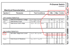
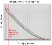
Either your measurement setup is incorrect, or you got an unlucky batch of devices. 10 minutes ago I pulled ten J175s out of my parts drawer and put them on the curve tracer. All ten were acceptably close to the 25mA IDSS requirement.
_
_
Attachments
- Home
- Amplifiers
- Pass Labs
- Ship Of Theseus: compatible, interchangeable amplifier modules