WTB: 2 ea. FQA36P15, IRFP250 (TO-247AC or TO-220AB style case, not TO-3), ROE-1205S
I am looking for the actives needed to build the Theseus-MOS output stages. For now I'm not looking for substitues, eg. IRFP240/9240, I've got tons of those. I also need PCBs, all of them, but I can have them made myself if necessary.
The backstory: Octopart showed RS as the only source with these in stock, but for some reason they won't sell to US customers without a resale license (and also they want $$$ for shipping & handling) and I don't have time this morning to call them & beg. I can get the smaller regulators and transistors elsewhere. Before I ask on the Marketplace, does anyone here have a set they're willing to sell?
I’ll be going through some boxes this weekend. I’ll be on the lookout.
I don’t have those PCBs.
I don’t have those PCBs.
Thanks glenv6, I've got a line on the parts I need now.@ranshdow - I am seeing the IRFP250 in stock at Mouser and the FQA36P15 in stock at Newark (ships from the UK).
Apologies if I am misreading your post…

Hi @Mark Johnson ,
I've got a question about the power rating of R2 on the Theseus-MOS OS boards. R2 carries the full current of the U1 regulator output across it, so if D1 is rated for 1.3W (or more), shouldn't R2 be similarly rated, even with the lower -5V across it? 4.7 ohms with -5V relative to ground across it could theoretically draw as much as 1.06A, so over 5W under worse case conditions?

I've got a question about the power rating of R2 on the Theseus-MOS OS boards. R2 carries the full current of the U1 regulator output across it, so if D1 is rated for 1.3W (or more), shouldn't R2 be similarly rated, even with the lower -5V across it? 4.7 ohms with -5V relative to ground across it could theoretically draw as much as 1.06A, so over 5W under worse case conditions?
In equilibrium the current in C2 equals zero. The current in C4 equals zero. The current in D3 equals zero. The current in C6 equals zero.
Only R2, D2, R6, and R11 carry nonzero DC currents in the equilibrium condition. And Kirchoff's Current Law gives the same answer as plain old intuition:
Calculate the current in D2, assuming VNEG = -5.00 volts. Then calculate the currents in R6 and R11, assuming VBE = 0.6 volts. Finally add up the currents on the right hand side of the equation above.
Now you can calculate the power dissipated by R2: it's current * current * resistance. I bet your arithmetic says that the power is less than a tenth of a watt.
_
Only R2, D2, R6, and R11 carry nonzero DC currents in the equilibrium condition. And Kirchoff's Current Law gives the same answer as plain old intuition:
- Current in R2 = (Current in D2) + (Current in R6) + (Current in R11)
Calculate the current in D2, assuming VNEG = -5.00 volts. Then calculate the currents in R6 and R11, assuming VBE = 0.6 volts. Finally add up the currents on the right hand side of the equation above.
Now you can calculate the power dissipated by R2: it's current * current * resistance. I bet your arithmetic says that the power is less than a tenth of a watt.
_
Attachments
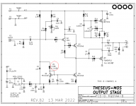
This I don't know how to do. My intuition tells me the resistance of D2 is functionally infinite with respect to any potentials across it, cathode to anode, of less than 12V. I don't know how much voltage is being dropped across R3, but if it was grounded and hence dropped the full 36V it's seeing, then the current it's passing is at most 20mA, and less with lower potential differences.Calculate the current in D2, assuming VNEG = -5.00 volts.
Similar problem for me. R3 and R5 in series to ground would pass at most 16mA, less with lower potentials. That current has to pass to ground through R6 and R11, presumably, which is another 25.7 ohms, which hardly changes the current passed. Still ~16mA?Then calculate the currents in R6 and R11, assuming VBE = 0.6 volts. Finally add up the currents on the right hand side of the equation above.
16mA at "VNEG" * -5V = 81mW across R2? Heck, I dunno. I studied biology, man.Now you can calculate the power dissipated by R2: it's current * current * resistance. I bet your arithmetic says that the power is less than a tenth of a watt.
_
Not sure why you read an honest question that way. I don't see anything in my tone implying confidence in a design error.Yet you were so confident that R2 was mis-designed.
Well now…After acquiring a signal generator, I was able to confirm that I hadn’t destroyed the Missouri boards other than one resister and one Capacitor. So I put the two boards back in the chassis and installed the XLR inputs. After triple checking my connections and doing another voltage check I put the amp back in the mix and it is running perfectly now. Sounding real nice and better as time goes along.
Big thanks to 6L6 for is building guides, Mark Johnson for the FE designs, and Nelson Pass for his generosity in his amp designs.
I can give some feedback after a bit of break in. I have been changing between one ACA, two ACA’s the Sony VFET with the Scourge FE and now this Missouri front end.
Big thanks to 6L6 for is building guides, Mark Johnson for the FE designs, and Nelson Pass for his generosity in his amp designs.
I can give some feedback after a bit of break in. I have been changing between one ACA, two ACA’s the Sony VFET with the Scourge FE and now this Missouri front end.
[Question of Amp board Voltage supply]
Hi
From the schematics of the Ship of Theseus, i kind of understand that only +36volts is used.
With linear power supply and amp like F5, M2x, i understood why we used +24volts and -24volts.
1) am i correct understanding that Ship of Theseus use only +36v?
2) if yes above, can somebody explain the difference between Ship of Theseus and others like First Watts amp?
Thanks in advance
Check post #1 of this thread:
The VFET kits that the Store shipped in June-August 2021 were designed by Nelson Pass, who also supplied the rare and long-out-of-production Sony VFET transistors from his vault of exotic semiconductors. NP discussed his VFET circuit design decisions on those amplifiers, in two articles found on the First Watt website (link).
Click on the articles called "2021 DIY Sony VFET pt 1" and also "2021 DIY Sony VFET pt 2"
- Ship Of Theseus is electrically compatible with the VFET kits that the Store shipped in June-August 2021. All of these amplifiers use the exact same +36VDC switch mode power supply in "brick" format. It is Mean Well part number GST160A36-R7B and is sold by several distributors, including the diyAudio Store (link to sales page).
The VFET kits that the Store shipped in June-August 2021 were designed by Nelson Pass, who also supplied the rare and long-out-of-production Sony VFET transistors from his vault of exotic semiconductors. NP discussed his VFET circuit design decisions on those amplifiers, in two articles found on the First Watt website (link).
Click on the articles called "2021 DIY Sony VFET pt 1" and also "2021 DIY Sony VFET pt 2"
- Home
- Amplifiers
- Pass Labs
- Ship Of Theseus: compatible, interchangeable amplifier modules