If your question is "Why did Nelson Pass design the VFET kit amps to operate from a single ended +36V power supply?" . . . . .
I think that's a question which only he can answer. He has posted a total of three messages in this thread, the most recent one was in April 2022, so I don't know whether he still reads here, or if he still does, how often. If he does not post a reply here, maybe you could ask in one of the VFET amp threads started by Nelson Pass himself. I bet there's a much greater chance he still reads threads that he created.
I think that's a question which only he can answer. He has posted a total of three messages in this thread, the most recent one was in April 2022, so I don't know whether he still reads here, or if he still does, how often. If he does not post a reply here, maybe you could ask in one of the VFET amp threads started by Nelson Pass himself. I bet there's a much greater chance he still reads threads that he created.
Yup, that would be it! I will follow your recommendations and go to the other thread.If your question is "Why did Nelson Pass design the VFET kit amps to operate from a single ended +36V power supply?" . . . . .
I think that's a question which only he can answer. He has posted a total of three messages in this thread, the most recent one was in April 2022, so I don't know whether he still reads here, or if he still does, how often. If he does not post a reply here, maybe you could ask in one of the VFET amp threads started by Nelson Pass himself. I bet there's a much greater chance he still reads threads that he created.
By the way, if somebody has 2xNimitz boards and channels A & B boards to sell and ship from Europe, i would be interested! ( please dm me)
regards
regards
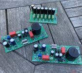
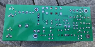
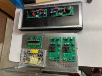
Soldering day. Thanks to an extraordinarily generous gift from a friend, I obtained pretty much all the difficult to obtain parts for the Theseus-MOS output stages. It took a couple more orders to gather up the resistors and such, and a day off of work to get these together. I'm pretty concerned with the potential for residual flux to serve as a weird conductor between traces so I put in some effort with acetone and a lot of Q-tips to clean it up. Next up, some output boards, likely Pequod, then layout in a chassis & wiring up.
Attachments

The only Theseus PCB with above-average sensitivity to leakage caused by PCB soldering flux, is the "Theseus PSFILT". That board has an RC delay circuit with a long, loooooong timeconstant, attached to a super high impedance MOSFET gate. So it benefits from special loving care when cleaning the board after soldering. See post #2 in this thread, third attachment.
But since you're not using Theseus PSFILT, those PSFILT-specific instructions don't apply to your build.
But since you're not using Theseus PSFILT, those PSFILT-specific instructions don't apply to your build.
Building Pequod. Realized I didn't order 8.2K ohm resistors for R7. Also realized I could make a pair of 8.32K ohm resistors from two metal film parts on hand, noting that this value is 1.4% off of spec (R7 is listed as a 1% tolerance part). @Mark Johnson will this value work acceptably? I'm guessing R7 serves to reference the feedback loop for U1 to ground, so the gain of the single op amp iteration might change?
Attachments
Let us pretend that message #226 says, Are there any readers who are willing to share their experience and knowledge, to answer: If I did WXYZ (see #226) would it work acceptably?
All members, please feel free to contribute and offer your opinions, guidance, and advice. Pretend the question has been addressed straight to you.
_
All members, please feel free to contribute and offer your opinions, guidance, and advice. Pretend the question has been addressed straight to you.
_
Attachments
I’m a neophyte, but with Mark’s encouragement in post #227, I’ll take a bite. Here is my thought. If you raise the resistance, you lower the current. In this circuit that change would amount to a minute rounding error that would not impact the negative feedback on the output of U1 in any material way - you won’t hear the difference. Hoping someone will check my assumption here…Building Pequod. Realized I didn't order 8.2K ohm resistors for R7. Also realized I could make a pair of 8.32K ohm resistors from two metal film parts on hand, noting that this value is 1.4% off of spec (R7 is listed as a 1% tolerance part). @Mark Johnson will this value work acceptably? I'm guessing R7 serves to reference the feedback loop for U1 to ground, so the gain of the single op amp iteration might change?
Theseus (and therefore Pequod) uses a single ended power supply: (+Posrail, GND). Thanks to the zener diode, Pequod's positive supply rail is about +24 to +26 volts. Comfortably lower than the Absolute Maximum Rating of supply voltage, for quite a large number of opamp candidates.
Since Pequod's bias resistors R3 and R4 are equal, they create a bias voltage at node "BARB" which is half of the positive rail voltage. BARB is around +12 to +13 volts.
The opamp(s) is a unity gain follower, its output voltage at node "DOUG" is equal to its input voltage. DOUG is around +12 to +13 volts.
Resistor R7 is connected between node DOUG and ground. The voltage across R7 is around +12 to +13 volts, so the current flowing in R7 (by Ohm's Law) is around 1.5 milliamperes.
The opamp's output pin sources a DC current of about 1.5mA, which flows thru R7 to ground. The important fact is: the opamp's output stage is biased at a DC current of about 1.5 mA, which flows to ground. So the opamp's output stage is (lightly) biased into Class A operation. Which eliminates an important source of distortion: crossover distortion.
The good news is, the amount of Class A bias current is not super critical, as long as it's not too low and as long as it's also not too high. I'd say that any amount of DC bias current between 1.25 mA and 3.0 mA would be just fine. Choose a DC bias current somewhere in this range, then use Ohm's Law to calculate the required value for R7.
Last edited:
Would anyone like to share their knowledge and experience, to give opinions and advice to a DIYA member, who asks:
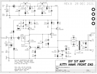
I've attached the Kitty Hawk schematic, below
I'm interested in the Kitty Hawk. How do I figure out the values of C6, R9, and R10 to alter the voltage gain? For example, if I needed.... 4X, 12db. Actually I'm not sure what the stock gain is, minus the transformer. Is there a brief tutorial somewhere? Simple formula? I've kind of been searching but I can't find anything.
I've attached the Kitty Hawk schematic, below
Attachments
Sorry I can't share my experiences on the kitty Hawk. My aircraft carrier is standing by. The ZTX957 will arrive in may.
Regarding post #232 - MarkU is in session! I will take another bite here with the usual caveat - Setting my embarrassment gene aside, I am no expert 
If I am reading the data sheet correctly, the bias range for Q2 is .710v - .850v. Assuming Q2 is fully on, biased to .850v without the voltage divider created by R9-R10.
Setting R9-R10 allows you to adjust Q2 bias from min to max, which alters the overall gain in Kitty Hawk. Setting R10 to 10k, the range for R9 would be 1.7k (Q2 fully on @ .850v) to 4k (Q2 just on @ .714v). Doing so varies the current through the series circuit Q2-J_TH, which in turn sets the stage for the bias of Q3 in the next stage.
I think C6 is there to block DC, so that could be set to .1uf.
So I think that answers the question, “How do I figure out the values of C6, R9, and R10 to alter the voltage gain”. This is where my thought process ends. Not only am I not sure about what I wrote above, I am also not sure about the approach to figuring out the gain Kitty Hawk produces.
Next!
Three of the VFET + Ship Of Theseus front end cards do not include a transformer: Marauder, Bulwark, and Lexington. Instead, these cards have a DC-to-DC converter onboard, which boosts the supply voltage by 25 volts or so, from approx. +36v to approx +61v. The higher supply voltage allows these front end cards to create a wide output signal swing, which is necessary to get full power output from the original VFET follower output stages. (Those output stages had a gain far less than one, thanks to the very low drain impedance of the Sony VFETs used).
Ten of the VFET + Ship Of Theseus front end cards do include an Edcor PC600-15K step up transformer: (Nelson Pass's original Lottery front end), Scourge, Bulwark, Relentless, Nimitz, Missouri, Bon Homme Richard, Kitty Hawk, Hornet, and Pequod. This transformer has a 1-to-5 turns ratio, meaning that the output voltage is 5x the input voltage, and the output current is (1/5)th the input current.
For the ten cards like Kitty Hawk that do include an Edcor, total front end voltage gain is the gain of the on-card preamp circuit driving the transformer, TIMES the transformer winding ratio. Thus
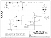
The easiest one to analyze is "Pequod" because its preamp circuit is a textbook classic "unity gain follower" circuit using an opamp. Thus for Pequod, (preamp gain) = 1.0 ; and
The analysis of the other nine front ends with transformers, proceeds similarly.
_
Ten of the VFET + Ship Of Theseus front end cards do include an Edcor PC600-15K step up transformer: (Nelson Pass's original Lottery front end), Scourge, Bulwark, Relentless, Nimitz, Missouri, Bon Homme Richard, Kitty Hawk, Hornet, and Pequod. This transformer has a 1-to-5 turns ratio, meaning that the output voltage is 5x the input voltage, and the output current is (1/5)th the input current.
For the ten cards like Kitty Hawk that do include an Edcor, total front end voltage gain is the gain of the on-card preamp circuit driving the transformer, TIMES the transformer winding ratio. Thus
Front End total voltage gain = (preamp gain) x 5.0
The easiest one to analyze is "Pequod" because its preamp circuit is a textbook classic "unity gain follower" circuit using an opamp. Thus for Pequod, (preamp gain) = 1.0 ; and
Pequod total voltage gain = (1.0) x 5.0 = 5.0 = +14.0 dB
The analysis of the other nine front ends with transformers, proceeds similarly.
_
Attachments

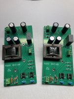
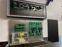
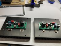
Playing with layouts today. While I have a Deluxe 4U chassis, I'm really reluctant to take down the amp in it, an F1J built with LU1014Ds, because it's working so well and won't fit in any other chassis I have due to PSU size. What I do have is a yet unused pair of the monoblock chassis that Modushop put out a year ago, so I wanted to see if a Ship of Theseus could fit in a single monoblock chassis. As one can see from the pictures, the layout is a little janky, but just might work. Sharing for the curious, will probably build this through to power-on, if not permanently.
Attachments

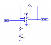
To analyze the "preamp gain" of Kitty Hawk, i.e., the gain of the circuits between connector P1 and capacitors C11+C12, all you need to know is that it's a (transconductance style) opamp. So it operates just like the other opamp circuits you've already analyzed. Even though the input differential pair happens to be an unorthodox "Rush Cascode" in this particular instance.

Capacitor C6 rolls off the response at super low frequencies, so that gain eventually falls to unity at DC. Then the output DC bias point is equal to the input DC bias point, which is (VTOP/2) thanks to equal value resistors R2 and R3. I suggest placing the rolloff corner frequency below 2.34567 Hertz, therefore
_
- Opamp "IN+" is the gate of the JFET
- Opamp "IN-" is the base of Q2.
- Opamp "OUTPUT" is the collector of Q4
- Opamp "Top Supply Rail" is node VTOP
- Opamp "Bottom Supply Rail" is node GND
- Preamp gain = 1 + (R10 / R9)
Capacitor C6 rolls off the response at super low frequencies, so that gain eventually falls to unity at DC. Then the output DC bias point is equal to the input DC bias point, which is (VTOP/2) thanks to equal value resistors R2 and R3. I suggest placing the rolloff corner frequency below 2.34567 Hertz, therefore
- C6 >= 1 / (R9 * 2.34567 * (2 * pi))
_
Attachments
Last edited:
Thanks Mark. Now il's clear how to increase the gain of the Kitty Hawk Front End.
Perfect for Sony VFET and the bigs SIT.
Perfect for Sony VFET and the bigs SIT.
I might make myself look stupid here... but anyhow.. So I think I could go R10= 20K, R9= 6.8K, and C6= 10uF. Gain of 11.9 dB (not counting the Edcor, I'm bringing my own Cinemag to the party). I like ~4X gain on the input stage of my SissySIT. A transconductance amplifier seems like it might work well driving a transformer, would like to try it..
Last edited:
- Home
- Amplifiers
- Pass Labs
- Ship Of Theseus: compatible, interchangeable amplifier modules