If anyone is in the UAE (and likes bright colours...) I have spare Missouri or PSFILT boards.
Shipping costs from here mean it'll probably only make sense to do locally, although if there's no rush I'd be in the UK towards summer and could post them there when I arrive 🙂
Thanks for this Mark, it's a wonderful thing you've done and I look forward to trying them out alongside some of the Scourge, Dreadnought batch!
Attachments
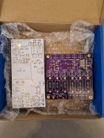
I received my Ship of Theseus boards from the supplier yesterday, all looks good so far. Not as pretty as others shown, they are green HASL with lead boards. I have been contemplating a front panel on / off switch for an amp build with the Meanwell supply and a S.O.T. filter board. Can the filter and muting relay "switch" supplies be supplied from the same DC switched source (SPST front panel switch), or must a DPST switch be used?
Are leakage current concerns the reason, or overload of the typical 5A "anti vandal" illuminated front panel latching switches the concern?
I can source a DPST 12A front panel switch, but they seem to run $50 plus when compared to the $10-15 single pole switches.
Sorry for my ignorance.
Are leakage current concerns the reason, or overload of the typical 5A "anti vandal" illuminated front panel latching switches the concern?
I can source a DPST 12A front panel switch, but they seem to run $50 plus when compared to the $10-15 single pole switches.
Sorry for my ignorance.
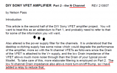
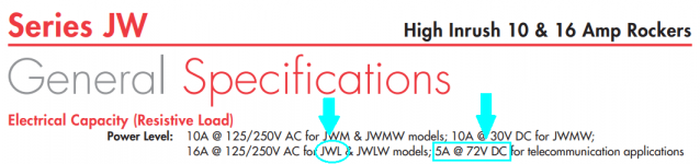
Ship Of Theseus is backward compatible with both of the VFET amps, and anyone contemplating building it should read Nelson Pass's thorough discussions of those VFET amps. To make that easy I have linked to his pdfs, in post #1 of this thread. I've also snipped an excerpt of page 1 of the Nchannel VFET technical paper, below.
The DPST switch which Nelson added to the N-VFET amp, is not a mandatory requirement -- its only purpose is to eliminate thumps at turn-on and turn-off. If you don't mind thumps, you can omit the DPST switch and simply use an SPST switch. However it is crucially important to select a switch whose manufacturer rates it for both (>35 volts DC switching) and (>4 amps DC switching). The DC rating is important, because switch contacts experience much worse arcing and pitting when switching DC, compared to switching AC. Contacts need to be much more rugged when they're called upon to switch DC, and that's what Theseus does.
Nelson's chosen SMPS is rated for 160 watts at 36 volts DC; that's a maximum output current of 4.4 amperes. So Theseus needs a switch rated for 36 volts DC (or more), AND 4 amps DC (or more).
However, some builders might stubbornly insist upon using their own favorite switch which has special & unique properties: it's beautiful, it's illuminated, it has a sexy "feel", it matches the switches on other equipment in the same rack, it's an iconic, classic switch pulled from an old Marantz or McIntosh or Audio Research or Levinson product, etc. And what options do these builders have, if their mandatory on/off switch is NOT rated for (>35V DC) and (>4 amps DC) ???
One option is to use that favorite switch on the front panel, to activate a beefy and muscular relay on a little outrigger circuit board inside the Ship Of Theseus chassis. The front panel switch only controls the coil of this relay, so the front panel switch contact ratings are very modest. Perhaps 12 volts and perhaps 0.1 amps. Then the relay on the outrigger board does all the heavy lifting. The relay provides DPST contacts rated for (>35V DC) and (>4 amps DC). Mouser offers quite a few suitable relays, in stock and ready to ship, that meet these requirements. Here is a list (prepared 19 March 2022):
(link to Mouser products)
You'd need to create your own little outrigger circuit board which mounts the relay you've chosen, and provides input-output connection points for the front panel switch, and for the relay contacts. Since relays with 36 volt coils are very difficult to find, you'll also need a voltage reducing circuit, to let Theseus's 36 volt supply operate your XYZ-volt relay without damaging the coil. Your relay coil might need 24 volts or 12 volts or some other number; whatever was cheapest at Mouser on the day you bought. The voltage reducer might be a resistor, or a zener diode, or an NPN transistor; it's completely your choice.
_
Attachments
Thank you for the teaching moment Mr. Johnson, and sorry I did not pre read the N channel article, only the P channel.
Sorry also for making you waste precious weekend time to answer my uneducated question.
Sorry also for making you waste precious weekend time to answer my uneducated question.
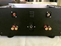
Here is the DPDT switch I'm using in the Ship Of Theseus amplifier that I built. It's made by NKK and is a member of their "JW" family of rocker switches; mine is Mouser part number 633-JWL22RAA . Mouser charged me $12.45 for it. You may be wondering why I bought the DPDT version with six terminals, since the PSFILT circuit (lifted from Nelson Pass's Nch VFET filter & enhanced slightly) only requires a DPST switch with four terminals. Simple answer: Mouser had the DPDT in stock, but the DPST was backordered. It was an easy decision!
Please notice that the model I bought, whose part number begins with "JWL", is DC rated (as required!). It's good for 5 amps DC at 72 volts DC . . . . . comfortably exceeding the requirements of the Ship Of Theseus amplifier.
Eagle eyed readers will quickly see that the Red (positive) loudspeaker output terminal for the Left channel, connects to more than one wire. Nicely spotted! One of those wires goes to the Left amp channel board (the MOSFET output stage), the other wire goes to the speaker muting relay on the PSFILT board. As you would expect after reading the Nchannel VFET design guide written by Nelson Pass, and linked in post #1 of this thread.
_
Attachments

Great! Thank youYes, the mounting hole pattern in the heatsinks is the same. The Sony VFET chassis is narrower, so will require some care in placement of the power filter board. As Mark said, the Theseus boards are backwards compatible. That includes mechanical considerations.
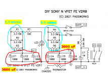
I've just finished building the PSFILT board and ran into a problem: The LEDs (both the one connected to the PSFILT and the one on the PSU) are blinking and DC fluctuates between 0 and 2V, but never reaches full V... The PSU is the Meanwell from the kit and worked flawlessly with the N VFET filter board before. Do I have a short? PCB looks ok as far as I can tell...
Looks like the Meanwell is burping on startup. Usually means more capacitance than it can handle on turn-on.
Same capacitance (3000 uF) on both boards so I don't think the Mean Well is entering "hiccup mode" on one but not the other. Hiccup is mentioned in datasheet, attachment 3.
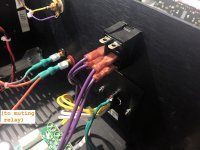
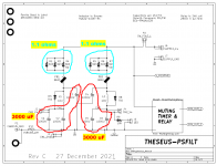
The fact that it rises to 2V suggests the problem may not be a dead short between supply and ground. Instead it sort of resembles an electrolytic cap installed backwards, with (+) and (-) terminals swapped.
edit- attached photo of silkscreen to easily see the correct orientation of 1000uF electrolytic caps.
_
Attachments

Last edited:
Sooo, I just took pictures and was about to upload them, when I decided to just try it again. And... it worked. The only thing I changed was cleaning off some cotton fluff from the bottom that was stuck from the cleaning process. Maybe that was it? Gave it a good blow with compressed air just in case. Odd... in any case seems to work now 😀 Thanks both!
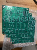
On a different note, I have 4 PSFILT PCBs left over to give away for packaging and shipping (based in Europe). If someone is interested let me know via PM.
Not as fancy looking as ElliotA's 🙂, but they're from JLCPCB, 2 oz outer copper weight.
EDIT: I may add that it works perfectly now. Shut-off thumb is barely there now, which is the main reason why I added it. VFET amp sounds fantastic as before obviously.
Not as fancy looking as ElliotA's 🙂, but they're from JLCPCB, 2 oz outer copper weight.
EDIT: I may add that it works perfectly now. Shut-off thumb is barely there now, which is the main reason why I added it. VFET amp sounds fantastic as before obviously.
Attachments
Hi,
the 2n7000 for the Psfilt seem to be out of stock at mouser. Any other mosfet that can do the same job?
Hubert
the 2n7000 for the Psfilt seem to be out of stock at mouser. Any other mosfet that can do the same job?
Hubert
If you're in the USA, I'll send you four 2N7000s in the mail. PM me your address. If outside the USA, try the "Swap Meet" section of the Forum, maybe someone in your country has spares.
I’m in Canada ! But thank you for your offer. I’ll try to find some locallyIf you're in the USA, I'll send you four 2N7000s in the mail. PM me your address. If outside the USA, try the "Swap Meet" section of the Forum, maybe someone in your country has spares.
Hubert
- Home
- Amplifiers
- Pass Labs
- Ship Of Theseus: compatible, interchangeable amplifier modules