replaced with 0.22uF polypropylene cap(not metalized) and 1000pF C0G MLCC paralleled , selected by actual measurement.
Just to add a data point, modern C0G caps using nickel electrodes and calcium zirconate dielectric are actually incredibly linear and predictable. Yes, polypropylene and polystyrene are great dielectrics, but the terminations of individual capacitors can sometimes go wrong, even with a "generally good quality" part, and can cause measurable distortion, just from defects in the termination of the foil/metallization to the leads.
I'm working with surface mount these days, and require tiny parts, so a 0.1µF C0G MLCC is about as big as I can use. However, they can be paralleled for larger values, they have zero microphonics, and their termination is absolutely reliable, as long as the part is not mechanically flexed so as to cause the body to crack. Because of this, they will all measure "perfectly", which can't be said of film caps.
Older C0G MLCCs used a different and somewhat inferior ceramic, but those ceramics required a precious metal electrode system, and cost a lot more. So, any modern, low cost C0G cap using a base metal (nickel) electrode system will use the calcium zirconate dielectric, and will perform extremely well. An example of a modern cap like that: the Kemet C1812C104J1GACTU is about $0.425 in 100s, and $0.375 for 1000. it's a 1.4mm thick 1812 chip, rated at 100V. It's pricey to stack up 10µF of capacitance using those, but for smaller replacements, like your 0.22µF cap, these are viable parts to consider.
How much? I'm glad I got mine before they were "discovered". With less than the comprehensive mods that Davida has done I am able to get -118 dB THD+N. However that's at 3V and 1 KHz. I don't know how close I can get at other frequencies or levels.
Last edited:
Just to add a data point, modern C0G caps using nickel electrodes and calcium zirconate dielectric are actually incredibly linear and predictable. Yes, polypropylene and polystyrene are great dielectrics, but the terminations of individual capacitors can sometimes go wrong, even with a "generally good quality" part, and can cause measurable distortion, just from defects in the termination of the foil/metallization to the leads.
I'm working with surface mount these days, and require tiny parts, so a 0.1µF C0G MLCC is about as big as I can use. However, they can be paralleled for larger values, they have zero microphonics, and their termination is absolutely reliable, as long as the part is not mechanically flexed so as to cause the body to crack. Because of this, they will all measure "perfectly", which can't be said of film caps.
Older C0G MLCCs used a different and somewhat inferior ceramic, but those ceramics required a precious metal electrode system, and cost a lot more. So, any modern, low cost C0G cap using a base metal (nickel) electrode system will use the calcium zirconate dielectric, and will perform extremely well. An example of a modern cap like that: the Kemet C1812C104J1GACTU is about $0.425 in 100s, and $0.375 for 1000. it's a 1.4mm thick 1812 chip, rated at 100V. It's pricey to stack up 10µF of capacitance using those, but for smaller replacements, like your 0.22µF cap, these are viable parts to consider.
This is excellent advice which I'd like to second. Modern C0G is the only dielectric where I yet have to see a single specimen with excess distortion. Certain film capacitors have lower distortion than a comparable C0G, but there is large specimen-to-specimen spread and the distortion behavior is often unsteady (e.g. mechanical stress may trigger excess distortion, or the distortion changes over time without further action). Even if they are selected, film does not seem a very reliable way for critical applications.
Samuel
How much? I'm glad I got mine before they were "discovered". With less than the comprehensive mods that Davida has done I am able to get -118 dB THD+N. However that's at 3V and 1 KHz. I don't know how close I can get at other frequencies or levels.
No worries Demian. The latest AP only gets the -120dB at 2V 1KHz. Otherwise -117dB.
As a THD+N comparison.... the simple mod HP-339A does slightly better than -100dB while the full mods get close to -105dB . This is comparable to sound cards or external ADC. The unmodified Panasonic (which also does individual harmonic measurements like the ShibaSoku 725) does -107dB.


No idea how to or why the 339 pictures is side-ways. But it is right when you open it. (?)
To get better results than these leaves only the ShibaSoku 725 or Audio Prcision's best. The cost rises fast to get the very lowest test data levels.
Notch filters and an FFT can be added to the monitor outputs of the HP or Panasonic, however, to extend the performance. The cost of the 725 is about the same or less than the Panasonic. But the newer A-P is a lot more expensive.
BTW -- the Panasonic does IM and FFT as does the A-P. But A-P does many, many other tests. But for straight ahead THD or THD+N and harmonics (to 5th), the 725 is It..... and with some mods as David determined, it is even better.
THx-RNMarsh
Last edited:
Richard
Are you using their own oscillators in the HPs and Panasonic?
Which oscillator are you using on the 725?
Are you using their own oscillators in the HPs and Panasonic?
Which oscillator are you using on the 725?
Yes, the internal osc for those two instruments.
I have several external osc....including Victors.
I like David's or anyone who can make a continuously variable freq osc of ultra low distortion. The variable freq is helpful in tuning for lowest distortion in some conditions. That is what I am looking for by those here designing oscillators.
The Panasonic THD (Not THD+N) is shown here with internal osc --->


These are stock.... unmodified units.
THx-RNMarsh
I have several external osc....including Victors.
I like David's or anyone who can make a continuously variable freq osc of ultra low distortion. The variable freq is helpful in tuning for lowest distortion in some conditions. That is what I am looking for by those here designing oscillators.
The Panasonic THD (Not THD+N) is shown here with internal osc --->
These are stock.... unmodified units.
THx-RNMarsh
Last edited:
Old story, Siemens's MKT caps distorts at new condition but is cured by burn in.
I learned it from audio magazine...
My AG16A's freq vernier started worsening distortion so I disabled it.poor quality pot!
and I did try and error and found some AG16A's GPIB commands.
to set frequency F******HZ or KZ and point is usable.It works without unit which is regarded as Hz.
to set attenuator A**.**
to enable/disable output O1 and O0
But, distortion rises after a command is sent. Just connecting cable to PC(via arduino GPIB) do not.why😕
deadlylover,Are these commands same as your AM51B?
Check the circuitry of the AG16. On the older version the level pot actually controls the AGC reference and its all DC. I also see odd distortion changing when I move the level pot. I really don't know whats happening. Its possible some stage is just outside its happy range when the level is increased. Otherwise its attenuator is all passive switching. On that unit the frequency pot on mine doesn't show any odd issues. Its been very useful for some other work I'm doing and may be essential for a proper alignment of the 725 notch filters.
The THD has been measured using the same signal source in the Panasonic 7722A and ShibaSoku AD725D for analyzer. Both instruments indicate -130-131 dB.

-RNM
-RNM
Last edited:
deadlylover,Are these commands same as your AM51B?
Shinja, I will check later. The AM51B manual I have doesn't show the GPIB commands listed, but I will experiment a bit, maybe they are similar to Panasonic's?
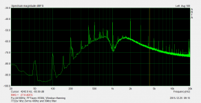
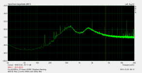
I took some quick and dirty monitor out spectrums of the Panny 7722A and the AM51B just for quick reference before I start tinkering inside. They are both using their internal oscillators. 0dBFS on ARTA corresponds to about -80dB (again, don't read too much into them, I'm not using a proper audio interface yet).
The AM51B looks pretty decent at first glance, interesting that it's missing the ~400-500Hz clock that the 725's use. There's some funny business at ~13kHz that I'll have to track down and tame.
I think the poor Panasonic desperately needs to be recapped and the notch filters retuned (same as the AM51B, a bit of the fundamental starts peeking through at anything above 1kHz). I'll post a BOM of the things needed to recap both units when I'm done with the teardowns. 😱
The AM51B is a bloody beast internally, the whole thing is shielded with little holes for you to stick your trimpot adjust tools in, it won't be as easy as the 725 to take apart. The card assemblies are missing the little plastic tabs used to lift them out, so I'll have to shove a paperclip in the PCB holes to lift the cards out.
Okita still sells the relays used for the 725B, mine is a sick puppy, I'll ask them for pricing later but I'm not expecting them to be cheap. 🙁 I kind of want to just use some COTO relays and bodge in suppression diodes, but I think the 725 deserves a bit better. =P
I'll get around to servicing/modding these units after the holidays, take care everyone!
Attachments
Check the circuitry of the AG16. On the older version the level pot actually controls the AGC reference and its all DC. I also see odd distortion changing when I move the level pot.
Demian, I would expect the distortion to change when you control the AGC level. After all, you are changing the loop gain of the thing.
IIRC Victor's oscillator works similarly (changing the AGC level when changing output level) and show similar behaviour.
Jan
Demian, I would expect the distortion to change when you control the AGC level. After all, you are changing the loop gain of the thing.
IIRC Victor's oscillator works similarly (changing the AGC level when changing output level) and show similar behaviour.
Jan
The total range on the generator for the fine adjust is +/- 1 dB. That should not cause big distortion jumps unless the whole system is at the verge of clipping, which it may be. On mine the 2nd seems to increase when I go from -1 to +1. I'll try to figure out how much. Its below the -120 level (lowest calibration) so I'm not sure.
The total range on the generator for the fine adjust is +/- 1 dB. That should not cause big distortion jumps unless the whole system is at the verge of clipping, which it may be. On mine the 2nd seems to increase when I go from -1 to +1. I'll try to figure out how much. Its below the -120 level (lowest calibration) so I'm not sure.
Agreed. The Victor uses the AGC als the level control so there the effect is more pronounced.
Jan
The THD has been measured using the same signal source in the Panasonic 7722A and ShibaSoku AD725D for analyzer. Both instruments indicate -130-131 dB.
-RNM
Richard,
I found instructions for using the Panasonic 7722A.
Since you use yours from time to time,
I'm wondering if you would be kind enough
to give us your insight on these instructions.
My biased opinion is that it's so full of bull_ _ _ _,
that the site/author's eyes (if there is one) are brown.
It this even possible?
How to Use a Panasonic VP-7722A | eHow UK
Cheers,
did somebody get paid to write that BS? its totally irrelevant to the analyzer. if someone needs instructions on what to do with an audio analyzer s/he is in way too deep. Its like getting a chassis dyno and not knowing how to set the idle on a car.
I not sure it's worthy of a response but what Demian said.
I left a comment on the linked page regarding the articale.
I left a comment on the linked page regarding the articale.
Richard,
I found instructions for using the Panasonic 7722A.
Since you use yours from time to time,
I'm wondering if you would be kind enough
to give us your insight on these instructions.
My biased opinion is that it's so full of bull_ _ _ _,
that the site/author's eyes (if there is one) are brown.
It this even possible?
How to Use a Panasonic VP-7722A | eHow UK
Cheers,
Last edited:
Richard,
I found instructions for using the Panasonic 7722A.
Since you use yours from time to time,
I'm wondering if you would be kind enough
to give us your insight on these instructions.
My biased opinion is that it's so full of bull_ _ _ _,
that the site/author's eyes (if there is one) are brown.
It this even possible?
How to Use a Panasonic VP-7722A | eHow UK
Cheers,
It doesnt seem like the author ever used it or any other analyzer before. IMO
-RM
Well, folks, the reaL deal:
https://www.dropbox.com/s/d8y0u1ohukjuq8j/Panasonic vp7722a manual.pdf?dl=0
https://www.dropbox.com/s/d8y0u1ohukjuq8j/Panasonic vp7722a manual.pdf?dl=0
- Home
- Design & Build
- Equipment & Tools
- ShibaSoku Automatic Distortion Analyzer