Got AM70A at dirt cheep price.
At first glance it is alright.
Its oscillator is almost same THD as AG15A , measured with 725C , at 1kHz 3Vrms about 0.00005% in analysis mode.
Analyzer section is worse distortion than 725C , residual D+N (not analysis ,30kHzLPF 400HzHPF ) is 0.0003% at 1kHz 2Vrms (not 3V due to ALC transision level) and much worse at higher frequency , even with AG15A used as source.
looked inside ,it is soooo much more complicated than 725C , AG15A and even 725D pic sync posted , card multi layer PCBs filled with a lot of components , more than half are SMD... but it looks state variable type oscillator and 3 stage bridge T BEF that is same as former.
It must hard, may impossible to find out distortion source of analyzer.
Last edited:
The box is big but that is still a lot of analog stuff to fit in. i suspect it has a more involved microprocessor running it to get the displays etc. Your numbers look like it meets spec. At least the price was right.
I would be interested in seeing some pictures. Getting a manual out of Shibasoku seems impossible.
I would be interested in seeing some pictures. Getting a manual out of Shibasoku seems impossible.
Here is the data sheet http://www.shibasoku.com/download/avc/am70a_e.pdf it does seem to meet specs.
Yes it meets its spec but 725 outperforms its spec so I expected too much on AM70A.
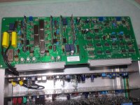
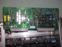
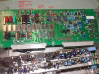
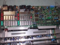
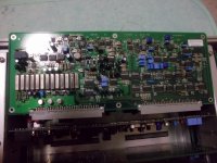
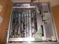
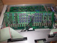
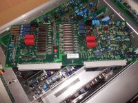
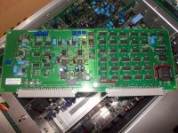
here are some pics
A1 A2 input , A3 BEF1 and IMD , A4 BEF2,3 (so heavy board!) A5 filter and detector
A6 and rest are not yet taken.
here are some pics
A1 A2 input , A3 BEF1 and IMD , A4 BEF2,3 (so heavy board!) A5 filter and detector
A6 and rest are not yet taken.
Attachments
The box is big but that is still a lot of analog stuff to fit in. i suspect it has a more involved microprocessor running it to get the displays etc. Your numbers look like it meets spec. At least the price was right.
I would be interested in seeing some pictures. Getting a manual out of Shibasoku seems impossible.
Shibasoku does not even answer my email about getting cal instructions.
The 725's are history. But I guess if they still use the same technologies in new analyzers they want to protect that.
Maybe I should just apply for a job there. But then I might have to sign NDA.
Yes it meets its spec but 725 outperforms its spec so I expected too much on AM70A.
here are some pics
A1 A2 input , A3 BEF1 and IMD , A4 BEF2,3 (so heavy board!) A5 filter and detector
A6 and rest are not yet taken.
Even though it does not meat performance of the 725 it is a beauty.
Thanks for the pictures. I'm sure others will appreciate them as well (Test equipment porn?)
I think Shibasoku is really out of the audio biz. The video biz has collapsed on them with it going digital there are not a lot of complex tests that need to be done except at the IC design phase which would sell maybe 10 boxes of anything ever.
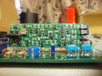
Many of the bits of the AM70 look like the 725D. I suspect the discrete opamp is the same circuit they have been using since the beginning. The large part next to the trimmer may be a dual Jfet and the trimmer would be DC offset at the input.
Tweaking it to get improved performance may be as simple as swapping a few 5534's, the same as the 725 BEF's. The oscillator would need tweaking as well. Its more the limitation than the analyzer. And I suspect that can be traced to the analog multiplier or leakage from the sample and hold (it seems to be the same discrete circuit that is in my really old oscillator). The discrete opamps are used to get the level up to 10V, not possible with integrated opamps.
I would probably by one if it was affordable and tweak away. GPIB would enable PC control.
I think Shibasoku is really out of the audio biz. The video biz has collapsed on them with it going digital there are not a lot of complex tests that need to be done except at the IC design phase which would sell maybe 10 boxes of anything ever.
Many of the bits of the AM70 look like the 725D. I suspect the discrete opamp is the same circuit they have been using since the beginning. The large part next to the trimmer may be a dual Jfet and the trimmer would be DC offset at the input.
Tweaking it to get improved performance may be as simple as swapping a few 5534's, the same as the 725 BEF's. The oscillator would need tweaking as well. Its more the limitation than the analyzer. And I suspect that can be traced to the analog multiplier or leakage from the sample and hold (it seems to be the same discrete circuit that is in my really old oscillator). The discrete opamps are used to get the level up to 10V, not possible with integrated opamps.
I would probably by one if it was affordable and tweak away. GPIB would enable PC control.
The large part near the trimmer is a 2SK389. The output transistors are off board in TO126.
Got one of these on the 725D A1 board as a summing amp for the two discrete balanced amplifiers. The trimmer is the offset trim.
Got one of these on the 725D A1 board as a summing amp for the two discrete balanced amplifiers. The trimmer is the offset trim.
Maybe we can include several other brands here when they use the same over-all design concepts/topology as the ShibaSoku .... namely the Panasonic industrial models, such as the VP-7722A
Inside it is much the same build and look as these shown here so far. Costs are reasonable, especially considering they include an ultra-low distortion generator. Greater availablity, and schematics are available and easier to get than ShibaSoku.
Modifications and improvements should work for them as well.
Here is the front panel display shown measuring its own generator.
 1KHz THD
 1KHz THD
 10KHz THD
 1KHz THD+N
Whah choo tink? same same. Got potential as alternative ShibaSoku.
THx-RNMarsh
Inside it is much the same build and look as these shown here so far. Costs are reasonable, especially considering they include an ultra-low distortion generator. Greater availablity, and schematics are available and easier to get than ShibaSoku.
Modifications and improvements should work for them as well.
Here is the front panel display shown measuring its own generator.
1KHz THD 1KHz THD 10KHz THD 1KHz THD+NWhah choo tink? same same. Got potential as alternative ShibaSoku.
THx-RNMarsh
Last edited:
click on the picture to blow it up.... -130dB is THD..... Not THD+N.
Analyzer appears to go to -140 max. This is stock and without a new tune-up/cal.
-RNM
Analyzer appears to go to -140 max. This is stock and without a new tune-up/cal.
-RNM
found problem with AM70A.
On both channel, ALC become crazy when input is below circa 300Hz, which frequency bit varies with input amplitude.
Relays around inpedance converter amp switchchchchchhchches back fast ,wasting contact life.
I must purchase PCB connectors to make raiser cable to investigate.
On both channel, ALC become crazy when input is below circa 300Hz, which frequency bit varies with input amplitude.
Relays around inpedance converter amp switchchchchchhchches back fast ,wasting contact life.
I must purchase PCB connectors to make raiser cable to investigate.
On the ALC detector board there is a circuit that changes the integrator depending on the input frequency. Do you have schematics or documentation? I can provide it for the older unit and it seems the circuits are largely unchanged except for a few detail revisions.
There is not a lot of current through the relays so they won't degrade or fail too fast but its not too useful either.
The extension board will be difficult to find and not easy to make. Douglas Electronics, here, has a kit for a eurocard extender. I figured out that two of those plus two male and two female 2 row eurocard type connectors would work.
The 725D does this with the relays as well.
I thought something was wrong when I first heard this.
There was a lot redesigned on this model and speeding up the
gain relays on the A1 board is one of them. The system is driven by a low frequency clock.
If you can find the clock you can lower the frequency.
The 725C is more reasonable with the relay switching.
Maybe Shibasoku is trying to clean the contacts when the unit is first turned on.
Who knows.
I suspected peak detector discharger clock too, and traced around there.
Detectors are bit changed from former than 725C, full wave rectifier with UPC813 (NEC's opamp) , TL071 and AD744, peak hold CR , discharger 2sk1061 ,TL071 buffer ,and LF398 sample hold amp which is not used in former.
Discharger and SHA clock is coming from 4538 one shot trigger, then CR and 4069 inverter oscillator which R is switched by 4052 analog switch .Its control signal is coming from other board.
Input attenuators and impedance converter gain switches are also bit changed, they are both ladder circuit. Attenuators are -10, -20 , and -30dB with two 2C relays. Amp gain is 0dB to 37.5dB in 4bit 16steps, 2.5dB per step.
guessed from traced circuit.
That amp gain range seems too large. The older design was 6 to 26 dB. However they may have needed to make some changes to accommodate the differential input. Let us know if you get to the root of the clicking relay issue.
Okay so it's essentially the same as the 725B/C/D. Just using what ever parts are available.
Most of the parts where changed to save space on the PCB. Some circuits were consolidated by sharing there function with other boards. Example of that is the AVG peak detector that disappeared from the A! board.
IIRC the sample reset clock on the A2 board of the 725 is < 10HZ.
Most of the parts where changed to save space on the PCB. Some circuits were consolidated by sharing there function with other boards. Example of that is the AVG peak detector that disappeared from the A! board.
IIRC the sample reset clock on the A2 board of the 725 is < 10HZ.
Last edited:
- Home
- Design & Build
- Equipment & Tools
- ShibaSoku Automatic Distortion Analyzer