Got permission from Papa to post gerbers.
I will do one last check of something and will post soon.
BOM for those who love BOM's will be tomorrow or day after tomorrow.
Why not a Group Buy?
Why not a Group Buy?
Now anyone can start a mini group, International or localy.
Order a few boards for self and ofer excessive boards to others.
It depens if you are happy with chosen:
1. Copper thickness. (It should be 70um copper or 2oz in some factorys)
2. Surface Finish. (ENIG or HASL) (If I were you I would have chosen ENIG 🙂)
3. Solder Mask color. (Green or Blue should look nice I tink)
4. Board Thickness. (Usualy 1.6mm by default. 2mm would be extra nice)
5. Chosen or not extra $ option to remove pcb product number almost all fabric add on boards.
Why not me?
I have some things going on in life so I could not handle it.
Not now and probably not soon..
But having gerbers is a win win win and I am glad that Papa gave his permission to share them.
P.S.: A little reminder. No one have boards made and tested yet. Please consider it a beta testing. And if everything goes well (and I am confident it will) you can start a bigger group buys.
Gerbers V1.01 with a minor fix.
While doing BOM I found popular purple Panasonic 3W resistor dimensions are L15.5mm x D5.5mm.
And in KiCad it was chosen "Resistor_THT:R_Axial_DIN0516_L15.5mm_D5.0mm_P20.32mm_Horizontal"
I also change their color in KiCad to resemble Panasonics but real Panasonics are 0.5mm wider.
It means silk screen for those are 5mm width.
Dimension between output resistors is exactly 5.5mm wich means Panasonics will fit but less place for "breath".
I widen distance to 6mm between resistors not changing the silkscreen.
Vishay / Dale CPF3 for example have dimensions L14mm x D4.57mm
It's only Panasonics are chonky.
Am I worry too much on a small things? )
P.S.: Nice gerbers viewer: Online Gerber Viewer - PCB Prototype the Easy Way - PCBWay
Attachments


Thank you!
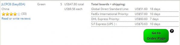
Board seem to have dimensions of 255.1 x 60.1 mm and DKRed are limited to 254 x 254 mm size.
So it would require to trim edges a bit, not a problem.
A problem is DKRed settings is limited to 1oz copper. You would need 2oz copper for high current boards.
So it would require to chose default board option on Digi-Key site and then manualy chose all board options.
Version with cut size to 254mm length in attach.
Attachments
to throw a curve ball here: I set out to make 4-channels of Aleph Mini (as sort of an upgrade to 4 channels of ACA currently used). The rails are going to end up at +/-15V min (probably around ~16-17V with my current grid voltage).
Is Aleph J mini (with SS fets) doable?
The mini would drive a speaker section with ~6 Ohm impedance. So the output power would probably be a little less? than that of the regular Aleph Mini but I would hope for a little more "sparkle" in tweet region on top of an already warm Aleph mids.
The chassis (for 2 channels) would be the new one currently designed for the Vfet anniversary amp: 4U 300mm deep chassis (0,31 C°/W).
Last edited:
RainskyFall - Thank you! This looks wonderful. I have some extra store Aleph J boards, but I think the SS parts may deserve their own board design.
GnuB - LOL! I just did a quick run through right before you posted.
I did 20 boards with the following attached. I used the larger boards. The US manufacturers were not competitive re: price. Still on the fence. If there are others interested in RSFs boards, we can decide re: a GB. I could host for US, perhaps.
Note, I am still on the fence re: what to use the SS with, but ... I thought I'd put it out there.
to throw a curve ball here: I set out to make 4-channels of Aleph Mini (as sort of an upgrade to 4 channels of ACA currently used). The rails are going to end up at +/-15V min (probably around ~16-17V with my current grid voltage).
Is Aleph J mini (with SS fets) doable?
The mini would drive a speaker section with ~6 Ohm impedance. So the output power would probably be a little less? than that of the regular Aleph Mini but I would hope for a little more "sparkle" in tweet region on top of an already warm Aleph mids.
The chassis (for 2 channels) would be the new one currently designed for the Vfet anniversary amp: 4U 300mm deep chassis (0,31 C°/W).
yes
..Is Aleph J mini (with SS fets) doable?
In this case I will also take a pair of boards please (whoever gets the GB going). Thx 🙂.
@ZM: What values do you expect will need tweaking for my rail Vs? so I can order the rest of the BOM posted here right away I guess.
practically no changes
but really don't go bellow 15Vdc
maybe you'll need to tweak few resistor values for 1A Iq, but we'll paint that bridge when we arrive there
think about possible small pcbs, now tested, if that format suits you more
but really don't go bellow 15Vdc
maybe you'll need to tweak few resistor values for 1A Iq, but we'll paint that bridge when we arrive there
think about possible small pcbs, now tested, if that format suits you more
Not that it's not obvious but with HASL finish pads and some board arts would be "metallic" color.
I thought that I should have say that in case it's not so obvious.. 🙂
It seems the PCB is being taken seriously and I really appreciate the time that went into its design, so well done and thank you for sharing.
I have one remark that should be carefully considered, and few minor remarks...
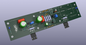
The first one: separate the 4 x large resistors' area on the PCB (used to generate the voltage drop for AC gain by CCS) from the input differential JFET pair and associated resistors, a capacitor and a diode. The best thing to do is to place the input differential pair at the end of the board - close to C1. You should make a mirror image PCB's, to ensure that the input hook-up wiring (from the RCA sockets to the AMP PCBs' input eyelets) is as short as possible for either AMP PCB. See how Nelson does it inside his FW amps. You'll notice the input hook-up wiring loom (length) is very short.
Not only that you will be minimising the input hook-up wiring loom (length) that is exposed to hum and noise, you will ALSO be separating the input section from the high current output section. At the moment, these two sections are very close together - Aleph J is a very wide band, very high input impedance design and hence - the close proximity of the high current section to the input JFET's section could cause oscillations. It is better to keep them separate.
I think I saw already a PCB design of yours where you had the input section placed close to the C1 - use that as a starting point.
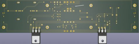
The next remark…. you could use vias to connect both sides of wide copper traces that handle power rails‘ currents, and the speaker outputs‘ current (to the speaker lug)
The last one relates to where exactly you’ll be picking up the NFB signal, and the AC gain for CCS signal from. Have a look at before / after photos and you’ll see what I did. The required alteration is minimal. This will ensure that the THD is as low as possible (all other things staying/being the same…)
See if Nelson wants to have a look / have his say.... That would be the ultimate check 🙂
Other than these (above) I really like what you did and I would definitely use your PCB's.... if I ever get hold of two SemiSouts one day.
Regards,
Nick
Attachments

It seems the PCB is being taken seriously and I really appreciate the time that went into its design, so well done and thank you for sharing.
I have one remark that should be carefully considered, and few minor remarks...
Regards,
Nick
Thank you for suggestions Nick!
I will try to absorb incoming information.
First remark is partly possible. I can move inputs and jfets closet to C1.
But mirroring boards to left and right channels last time I tryed was hard for layout beginer so it was chosen to make them exact same like store boards did.
As added plus I expect them behave the same and possible to compare with a good one in case of ever troubleshooting.
I will try to mirror board(s) in future. Need more time to experiment, more experience.
They were were even closer on my first layout. 😱 😀
Only in Aleph J-X I had them very far away at the centre of the board.
Second remark sounds easy but I want to specify a few things.
What would be the optimal way to connect those traces to speaker output?
I have a few options on the pictures in attach.
Attachments


...
think about possible small pcbs, now tested, if that format suits you more
Thx. Maybe I can get the smaller format Aleph J pcb which P. Daniel made long time ago and drop some of the outputs? I posted in swap meat to see if there are any.
p.s. I stopped designing pcbs since the software I used before is no longer available to me, plus the time needed is always a concern.
I don't see any problem with leaving the layout identical for both channels. Slight differences in wiring will be insignificant and invisible once the top cover is installed.
The best thing an amp builder can do is construct a proper dual-mono power supply. The Aleph J is a special amp, and makes excellent use of good channel separation.
The best thing an amp builder can do is construct a proper dual-mono power supply. The Aleph J is a special amp, and makes excellent use of good channel separation.
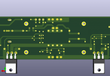
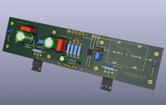
Atempt was made to move JFET pair closer to C1 and different tracing to speaker output suggested by Extreme_Boky.
Higher density of components near C1 now.
But I am not ready to make mirror boards yet. Sorry.
What do you think guys?
It looks like a simple change but it took a lot of time.
I tryed various layouts I was not happy with.
Stayed with this one.
Higher density of components near C1 now.
But I am not ready to make mirror boards yet. Sorry.
What do you think guys?
It looks like a simple change but it took a lot of time.
I tryed various layouts I was not happy with.
Stayed with this one.
Attachments

Mr. RainfallSky:
I am not qualified to comment, regardless... wanted to say thanks for your hard work. I was among we lucky few to receive a pair of SS devices and am following your efforts with much interest.
I have a set of the original boards because of near universal approval, but would be interested in obtaining a set of yours when/if you're ready to publish.
Great work! - David
- Home
- Amplifiers
- Pass Labs
- Semisouth Aleph J?