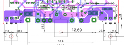
Atempt was made to move JFET pair closer to C1 and different tracing to speaker output suggested by Extreme_Boky.
Higher density of components near C1 now.
But I am not ready to make mirror boards yet. Sorry.
What do you think guys?
It looks like a simple change but it took a lot of time.
I tryed various layouts I was not happy with.
Stayed with this one.
Looking really nice! Did you consider duplicating your higher current traces on the second layer?
Cannot do that because the connection from Q1 to Q2 is in the way ... but you can actually remove that entire section out from the middle bottom of the board and shove it over by C1 ...
Then you would be able duplicate the high current trace on the other layer (possibly)
Then you would be able duplicate the high current trace on the other layer (possibly)
Nice Work!
That looks really nice. Well done.
Atempt was made to move JFET pair closer to C1 and different tracing to speaker output suggested by Extreme_Boky.
Higher density of components near C1 now.
But I am not ready to make mirror boards yet. Sorry.
What do you think guys?
It looks like a simple change but it took a lot of time.
I tryed various layouts I was not happy with.
Stayed with this one.
That looks really nice. Well done.
Great work! - David
That looks really nice. Well done.
Thank you!
Looking really nice! Did you consider duplicating your higher current traces on the second layer?
Cody, сan you please scpecify what exact traces you think need doubling?
I expect biggest current flow in the + and - rails. They are already doubled and also GND doubled too.
Or you meant trace between SJEP120R100 gate and R13 resistor to output resistors?
Q2 collector to Q1 trace is in a way for that.
But it is possible to compomise with added jumper for that trace.
Would that be better or not I am not realy sure.
Or I coud make sliiiiiiiim widening of SJEP120R100 gate trace.
I was just thinking the connections to the source and gate of the output devices. I recently worked up an Aleph J/SS -ish board with Prasi. and I noticed he made those traces fairly big, and doubled up when possible.
Take all this with a grain of salt. I think you have a fine layout, and I don't think any of these things are essential – more just ideas if you're looking to tweak further.
Take all this with a grain of salt. I think you have a fine layout, and I don't think any of these things are essential – more just ideas if you're looking to tweak further.
Attachments
Prasi is a Pro. 🙂
I have his PSU boards at home. 😀
I will leave my boards as is for now.
Edit:
And so many people making Aleph boards. Who would have thought.
I should have wait and borrow good ideas. 😀😀😀
I have his PSU boards at home. 😀
I will leave my boards as is for now.
Edit:
And so many people making Aleph boards. Who would have thought.
I should have wait and borrow good ideas. 😀😀😀
Last edited:
Yeah, he's definitely a pro. But props to you for doing these layouts on your own. I took the easy way out, as I'd started to lay these out myself but then bailed and contacted Prasi to take over 🙂
Edit: before too many people contact me about these boards, please know that I didn't make these with a group buy in mind, and they're made with my very specific interests, parts, and design decisions in mind. In other words, I was only trying to please myself. On the other hand, RainfallSky has made a beautiful layout for public consumption, and his design decisions should appeal to lots of people. If I were you, I'd consider using his boards 🙂
Edit: before too many people contact me about these boards, please know that I didn't make these with a group buy in mind, and they're made with my very specific interests, parts, and design decisions in mind. In other words, I was only trying to please myself. On the other hand, RainfallSky has made a beautiful layout for public consumption, and his design decisions should appeal to lots of people. If I were you, I'd consider using his boards 🙂
Last edited:
Looks great! It just occurred to me – you could move the old man over and give him a bright, blue eyeball 😀
Looks great! It just occurred to me – you could move the old man over and give him a bright, blue eyeball 😀
Too big for an aye. But he will shine in the light of the LED. 🙂
Zeus. God of high current lightnings and boomy thunders. 😀
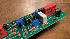
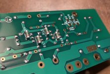
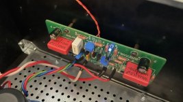
Got my boards finished up today. I’ll post some more details in the next day or two, but here are a few pics in meantime.
Attachments
-
 CD978578-CE3F-457C-AB77-AEA6CD04D138.jpeg174.6 KB · Views: 324
 -
 82DE457A-16FA-417B-B093-FB5E1E2663E9.jpeg94.1 KB · Views: 316
 -
 CEA65A00-E1FC-40A8-B8C3-6FEBFE4D2B4B.jpeg85.8 KB · Views: 287
 -
 A33BE794-AD36-4326-86A2-4FDE638EF699.jpeg82.1 KB · Views: 287
 -
 359BC2C2-9106-4E3D-9897-A2DB04EC60A4.jpeg75.1 KB · Views: 291
Hello again Cody, sorry but I'm a bit confused... tought you already had a J with one SS. Is this another one or a rebuilt version?
This is just a different layout and slightly tweaked Aleph J/SS. Completely unnecessary 🙂
Once you have built a NP designed/inspired amp the rest are unnecessary, but we build more.
sweet! are you gonna be able to give us a direct comparison or did you have to steal the AJ chassis for these boards?
sweet! are you gonna be able to give us a direct comparison or did you have to steal the AJ chassis for these boards?
Yeah, I unfortunately have one chassis and many amp boards, so it’s always a game of swapping out channels. I will be able to compare measurements, and will share soon. To be honest, there’s really nothing different about it though, so not expecting huge changes. Just a tweak to the front end, and some other little changes here and there.
So you are using 2 parallel SJ74 per leg of the differential pair and reduced its drainresistor? What is the tailcurrent you are running?
With transistors, it is supposed to be beneficial to implement the same resistor in both legs of a differential pair to improve the matching... even if you don't need the second resistor. It also balances the power in the semiconductors of both legs. Don't know if that is significant though...
Thanks for all the sharing, Cody!
Got my boards finished up today. I’ll post some more details in the next day or two, but here are a few pics in meantime.
Waiting for sound impressions.

I like that part after all tech parts is done. 🙂

- Home
- Amplifiers
- Pass Labs
- Semisouth Aleph J?