Have you considered the constant current versus temperature ?
About the first CCS in the original post I found a quite high positive temperature coefficient.
In this ccs, the "constant current" increases with the temperature of a transistor.
Erratum: Read negative temperature coefficient
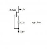
This CCS has a negative Temperature Coefficient:. - 0.02 mA / °C
At T= 27 °C........Ia=6.43mA
At T=127°C........Ia=4.55mA
Attachments
Last edited:
Hello!
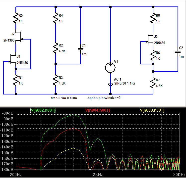
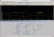
Doing some searches on low noise ccs and jFets I found this post but not being an LTSpice user I'm not sure how to line things up. Do green, red , yellow correspond to left, centre, right circuits respectively? And what is being indicated ? 1K injected signal dB down at output?
Thanks very much!
Hi,
I hope it's not too late to add a post here. It seems the right place to put my question. I' m looking for a suitable CCS for a tube LTP. Eventualy it could be something more complex but for now I need to keep it simple. So, I use the one on the attached schematic wich is the #2 on the OP schematic. Currently, I don't seek for megaohms in the ultrasonic spectrum. It just need to have a decent impedance across the audio range. I t doesn't even have to be linear as long as it doesn't drop drammatically. My biggest concern though is with regards to post #15 ;
Thanks...or sorry...Whatever...
PS. I tried to make my first steps on LTspice but on second thought I left it for the long winter nights!
I hope it's not too late to add a post here. It seems the right place to put my question. I' m looking for a suitable CCS for a tube LTP. Eventualy it could be something more complex but for now I need to keep it simple. So, I use the one on the attached schematic wich is the #2 on the OP schematic. Currently, I don't seek for megaohms in the ultrasonic spectrum. It just need to have a decent impedance across the audio range. I t doesn't even have to be linear as long as it doesn't drop drammatically. My biggest concern though is with regards to post #15 ;
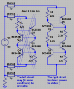
So, do you see any instability or speed issues in my CCS?Than i ran a transient analysis to check stability of these circuits.
I quickly rejected the "self cascoding", it has ringing like hell, asking for problems. Also i rejected all circuits showing any ringing or beeing ugly slow, this left over 3 circuits, the zener referenced ones and the cascoded jfet.
Number 7 (the cascoded jfet) seems to be best option regarding psrr AND stability. (the most stable one)
2nd choice would be Number 3, simple but efficient and stable. Better than my favourite (until today), the No1....
Mike
Thanks...or sorry...Whatever...
PS. I tried to make my first steps on LTspice but on second thought I left it for the long winter nights!
Attachments
Can the CCS see voltage spikes during start up, or shut down, or during some nearly normal abuse?
The CCS would need to survive these voltage spikes, if they ever occur.
The CCS would need to survive these voltage spikes, if they ever occur.
Hi, thanks for reply,
It is used at the cathodes - I should have mentioned this - and there is soft start (tube rectifier) for a 150V B+. After I installed it , soft start seems to be even softer but eventually it settles just right and very stable at least at idle. I was wondering about dynamic behaviour and if can be predicted from datasheet or any simple way not including an oscilloscope...
It is used at the cathodes - I should have mentioned this - and there is soft start (tube rectifier) for a 150V B+. After I installed it , soft start seems to be even softer but eventually it settles just right and very stable at least at idle. I was wondering about dynamic behaviour and if can be predicted from datasheet or any simple way not including an oscilloscope...
Hi Mike,
Do you have any indication of the source for the most right (4 BJT's) CCS?
Best regards,
Frans.
Do you have any indication of the source for the most right (4 BJT's) CCS?
Best regards,
Frans.
I am looking for an "ideal" ccs, i attached a small collection of 9 different ccs circuits, all rated with a psrr. This db value is the voltage ripple visible at the 1k resistor with the power supply contaminated with 1v AC, all ccs giving ~3ma. The LED style is missing because i have no model...
Did i forget other / better circuits ? Right now the cascoded jfet-ccs seems to be the candidate. Number 9 is also very interesting as it is floating style like a single jfet-ccs.
What i want is a ccs with high psrr, but not too complicated.
Mike
MikeB stopped posting many years ago, this thread was started 12 years ago.
Jcx's genius seems to have gone over most of our heads at the time.
The ideas I posted aren't very useful, it was 10 years ago after all. But in the time since then I have never actually needed a really good CCS to get good distortion in a power amp.
Jcx's genius seems to have gone over most of our heads at the time.
The ideas I posted aren't very useful, it was 10 years ago after all. But in the time since then I have never actually needed a really good CCS to get good distortion in a power amp.
I just wanted some historical background on this 4 BJT CCS. A few years ago I brought it in into one of Joachim Gerhard his amplifiers and also is some permutation of the MPP phono.
As I am sure that I used it first somewhere in the early 70's (or there about) and I did receive (lately) get some questions about this CCS, it seems useful to ask if someone has some background of it and it's historical origins.
As I am sure that I used it first somewhere in the early 70's (or there about) and I did receive (lately) get some questions about this CCS, it seems useful to ask if someone has some background of it and it's historical origins.
Since we’re discussing CCS design. I remember Walt Jung wrote two articles on the subject for Audio Express in 2007 which were available for download free of charge. I just tried finding them but it appears the links are no longer working? Or am I looking in the wrong place?
Hi Frans,
I built that circuit after seeing it in the JG Nobrainer thread using the same devices side to side and it works well. Just wondering what your thought was in choosing the dissimilar transistors you did.
Thanks
I built that circuit after seeing it in the JG Nobrainer thread using the same devices side to side and it works well. Just wondering what your thought was in choosing the dissimilar transistors you did.
Thanks
Attachments
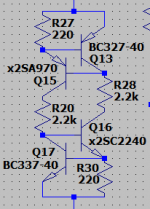
Some references and observations about the 4 BJT CCS as used in the 'Nobrainer' amplifier thread.
The historical origin of the circuit is not known to me (FdW)
First showing [in the Nobrainer thread] 🙂 (circuit on left side)
https://www.diyaudio.com/forums/ana...rainer-nobrainer-discrete-32.html#post3814466
Post# 312
Using: 2SA970 and 2SC2240
https://www.diyaudio.com/forums/ana...rainer-nobrainer-discrete-33.html#post3814605
Post# 323
https://www.diyaudio.com/forums/ana...rainer-nobrainer-discrete-33.html#post3815110
Post# 328
Problems in paradise
https://www.diyaudio.com/forums/ana...rainer-nobrainer-discrete-33.html#post3815110
Post# 356
Investigations
https://www.diyaudio.com/forums/ana...rainer-nobrainer-discrete-37.html#post3840886
Post# 362 and up
Solved (circuit on right side)
https://www.diyaudio.com/forums/ana...rainer-nobrainer-discrete-37.html#post3840956
Post# 366 The circuit shows a strange mix of transistors, this is no problem but unintended (not noted at the time)
The circuit works problem free in most, if not all, situations and configurations. Using transistors with a higher hfe will produce a better current regulation. Note that Vce(max) must at the least equal the power supply differential (from V+ to V- of the circuit, if not the circuit may have startup problems due to some form of thyristor behavior of the circuit.
Footnote
https://www.diyaudio.com/forums/ana...rainer-nobrainer-discrete-37.html#post3842898
Post# 370
Attachments
Last edited:
I think I saw this somewhere at the time. You don't need the 2 2.2k resistors, you only need one 1k resistor. You yourself discovered it was stable with 1k resistance in series. The behavior is nearly exactly the same. I don't think splitting the resistor between the two paths actually has any benefit.
Lower plots are dynamic resistance across 40V swing. The spikes are due to out of phase capacitive currents which disrupt the differentiation.
Lower plots are dynamic resistance across 40V swing. The spikes are due to out of phase capacitive currents which disrupt the differentiation.
Attachments
Last edited:
I think I saw this somewhere at the time...
But where 🙂 I just would like to know.
...You yourself discovered it was stable with 1k resistance in series...
I know 😱 it's just some illogical mental forse that likes the total symmetrical schematic (maybe it's worth a resistor) if not, your right 🙂
Some references and observations about the 4 BJT CCS as used in the 'Nobrainer' amplifier thread.
The historical origin of the circuit is not known to me (FdW)
First showing [in the Nobrainer thread] 🙂 (circuit on left side)
https://www.diyaudio.com/forums/ana...rainer-nobrainer-discrete-32.html#post3814466
Post# 312
Using: 2SA970 and 2SC2240
https://www.diyaudio.com/forums/ana...rainer-nobrainer-discrete-33.html#post3814605
Post# 323
https://www.diyaudio.com/forums/ana...rainer-nobrainer-discrete-33.html#post3815110
Post# 328
Problems in paradise
https://www.diyaudio.com/forums/ana...rainer-nobrainer-discrete-33.html#post3815110
Post# 356
Investigations
https://www.diyaudio.com/forums/ana...rainer-nobrainer-discrete-37.html#post3840886
Post# 362 and up
Solved (circuit on right side)
https://www.diyaudio.com/forums/ana...rainer-nobrainer-discrete-37.html#post3840956
Post# 366 The circuit shows a strange mix of transistors, this is no problem but unintended (not noted at the time)
The circuit works problem free in most, if not all, situations and configurations. Using transistors with a higher hfe will produce a better current regulation. Note that Vce(max) must at the least equal the power supply differential (from V+ to V- of the circuit, if not the circuit may have startup problems due to some form of thyristor behavior of the circuit.
Footnote
https://www.diyaudio.com/forums/ana...rainer-nobrainer-discrete-37.html#post3842898
Post# 370
Hi Frans
I remember these discussions.
In my amp I found the middle resistors needed to avoid oscillations....
I think I saw this somewhere at the time. You don't need the 2 2.2k resistors, you only need one 1k resistor. You yourself discovered it was stable with 1k resistance in series. The behavior is nearly exactly the same. I don't think splitting the resistor between the two paths actually has any benefit.
Lower plots are dynamic resistance across 40V swing. The spikes are due to out of phase capacitive currents which disrupt the differentiation.
Only one resistor ?
In what side of the circuit ?
Well, I don't know much about the theory behind it and have never taken the time to learn LTspice , so all I know about the circuit is from what I've built.
I tried the one resistor on top and also one at the output (capacitance buffer) but still got the self extinguishing "thyristor mode" or got oscillation and device failure.
I built the circuit with SMD BJTs and also with DIP14 array with tight layout (tried stoppers as well) and had the same problems. With the two Rs separating PNP and NPN it was stable and is still running in a phono stage four years later. (Knock wood!)
I suppose with Keantoken's input I'm going to have to go back to the drawing board and try the single 1KΩ again. I bet it will work this time. (mumble grumble : )
- Status
- Not open for further replies.
- Home
- Amplifiers
- Solid State
- Searching the "best" CCS