Another idea: series RC filter between the anode of the zener to the base of the transistor. 4.7kohms+100uF means very good filtering, and slow start.
sajti
sajti
Unfortunately no. I have no software on this PC, I use now. But it's simple: Simple RC filter between the zener, and the transistor. Series resistor, parallel capacitor
sajti
sajti
The Vas is a bigger problem in regard to PSRR. Even a fairly poor CCS in the LTP gives better rejection than a stage that is referenced to one of the rails!
Tim, principally you are right. Things look a bit different for symasym...
Attached is psrr for symasym with inputstage removed. (openloop) (green = positive, red = negative)
psrr is already >40db, plus symasym's feedback of nearly 60db the psrr would easily be >100db. There are enough amps that would be happy to have 40db closed loop... 😀
But any psrr artefact outside feedbackloop can't be compensated. Simming symasym with a virtual spice-ccs gives psrr >80db down to dc.
The negative psrr is here dominated by the ccs to the ltp, the positive can be fixed to the same level by cascoding the input devices.
Mike
Attachments
About the VAS vs PSRR...
Consider a standard Lin topology :
Diff pair -> current mirror -> VAS with Cdom -> buffer -> driver -> output stage.
If you wanna talk about PSRR you've got to consider where the crap coming from the power supply will enter the circuit :
* V- variations affecting the CCS biasing the input stage :
Moot point. This CCS doesn't need to sit on the V- rail ; it just needs to bias the input transistors correctly, ie. collector of CCS < diff pair tail. Just run it off a RC filtered supply from the V- rail.
Also note that this one is not corrected by feedback, but its effects should cancel if the input pair is well balanced and has a current mirror on top.
* V+ variations affecting the diff pair : it affects both transistors equally.
* V- variations affecting the VAS biasing current source : these should be corrected by feedback, if there is enough feedback at high frequencies. I'd say this one is important.
* V+ variations : the VAS sits on V+ but the major source of PSRR loss is in fact Cdom (read Self) which dominates the PSRR of the transistor and the current source below.
Again, running low-power stages (input + VAS) off RC-filtered supplies should do a lot for PSRR.
peufeu, you are absolutely right, and i run my symasym frontend from RC filtered supplies. But, these filters degrade for low frequencies...
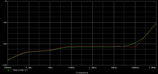
Anyway, i "solved" the problem, the question was as you pointed out, why the bias change was visible at the output. It shouldn't, as symasym runs perfectly balanced.
The solution: I replaced the input devices with jfets... Needs investigation...
Attached is actual psrr, green = +psrr, red = -psrr, nicely symetrical... 🙂
Mike
Anyway, i "solved" the problem, the question was as you pointed out, why the bias change was visible at the output. It shouldn't, as symasym runs perfectly balanced.
The solution: I replaced the input devices with jfets...
Needs investigation...Attached is actual psrr, green = +psrr, red = -psrr, nicely symetrical... 🙂
Mike
Attachments
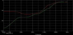
MikeB said:Ah yes, the ccs will be used to feed an input-LTP. In detail, i am trying to build a symasym with optimzed psrr to check the sonic advantages.
Attached is negative psrr of a symasym6, green uses standard 2-bjt-ccs, red cascoded jfet. As you can see, psrr degrades heavily below 100hz, also the normal ccs shows a resonance at 9mhz.
The peak at 13hz down shows that there is an additional problem...
As i want to publish schematic, i should avoid use of exotic parts, they would be substituted anyway.
Mike
Mike,
Some thoughts:
The bootstrapped jfet CCS is always a very good option for very
high OP Z. The bootstrapping fights against the miller capacitance
at higher frequencies which becomes + feedback.
Use gate stopper on bootsrap jfet.
All this is pretty academic anyway because which jfet has suitably
high voltage rating for this application aswell as a suitably high
vgs to allow headroom for the current setting jfet?
Stick with the bjt pair, split the 22k bias R into 2 x 11k. 100uF cap from middle of 2 x 11k to -PS rail.
Cheers
Terry
you seem to be confused, bootstrapping is not cascoding
in my earlier posts I show both
bootstrapping in this instance is moving the voltage of the "other" end of the current source the same as the "working" end at the diff pair emitters
This is easily done with a R divder with the same ratio as the feedback network, the bootstrap (small signal) voltage can match the diff emitter V to better than 99%, giving ~ 100x multiplcation of the ccs effective dynamic Z
my LtSpice sim doesn't use the best fets for this app, just the 1st pair I grabbed from the default part list
a real crd will get close to 10 MegOhm Dynamic Z, bootstrapping the crd would probably be sufficient for just about any requirement, cascoding and bootstrapping a crd with approprialy selectd fet would likely put ccs Z so high that pcb stray C impedance becomes the limiting factor over much of the audio band
jcx said:R5/R4 = R2/R1 (trimmed R4 for estimated D1 Zener dynamic Z of ~ 15 Ohm)
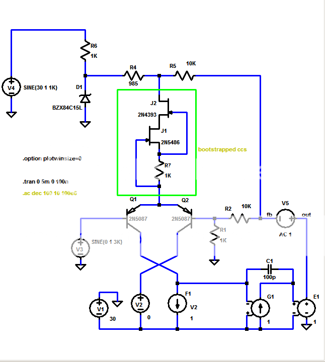
1KHz on V4 positive supply probes probes psrr
3KHz at V3 input tests input cmrr
plot Id(J2)*1000
for same display/"units" as earlier posts, ~ 115 dB psrr, 140dB input cmrr
jcx said:you seem to be confused, bootstrapping is not cascoding
in my earlier posts I show both
Not so JCX.
I know and have -used-, (not simmed) both. Some bootstrapped
circuits get their origins from Hawksford.
Your example shows in fact 2 bootstraps. 1) is, as you say, the
feedback R divider forcing theoretically zero voltage swing
across the CCS. 2) is actually the 2N4393 gate connected
to the 2N5486 source.
The R divider from OP is a neat idea.
Question is, have you tried it, what does it sound like, how does it
affect -actual- performance of amp?
Cheers
Terry
jcx said:
This is easily done with a R divder with the same ratio as the feedback network, the bootstrap (small signal) voltage can match the diff emitter V to better than 99%, giving ~ 100x multiplcation of the ccs effective dynamic Z
JCX, has any commercial amp used this arrangement?
It's definately a smart idea and worth a try.
Cheers
Terry
Terry Demol said:
Not so JCX.
I know and have -used-, (not simmed) both. Some bootstrapped
circuits get their origins from Hawksford.
Terry
How about changing "you're confused"
to
"you're confusing terminology that others in this thread have already agreed on"
when talking about ccs circuits I believe it is useful to make the distinction between the unambiguous term cascode to describe 2 transistor composites, and bootstrapping, which should be readily differentiated from the active cascode as a "passive" circuit technique that relies on a low impedance circuit node that has nearly unity gain with respect to your ccs load point
"C bootstrapped" resistor VAS ccs is the most commonly seen example, dates back to vacuum tube era, same with active cascode
it is fine to consider the underlying commonalty of the 2 approaches too but confusing to have to parse which circuit example you are referring to if you the term” bootstrap” for both
my literary friends solve crossword puzzles as entertainment, I sim discrete transistor audio circuits
my day job is designing precision instrumentation and usually the shortest distance between a transducer and a ADC is through one or more op amps
knowing how much time and effort I spend on debugging, testing, and verifying objective performance measurements in my professional designs I can only be envious of those who can just listen to their circuits and tell that they've improved it by tweaking a single subcircuit
vax9000 said:I read through this thread and I got confused. So what is the best CCS, as a conclusion?
Amplified negative feedback (ANF) current source (or sink).
Its output impedance is virtually identical to that of a cascode source, but uses only two transistors and two resistors.
😎
tvi said:I posted this sometime ago, you might find it of interest
Constant Current Source article (Old)
Regards
James
James, I used such sources to load vacuum triodes, istead of resistor between emitters I have sometimes to use a bleeding resistor ftom base of upper transistor to the ground, because when transistors are too good compared to Zeners the source won't start.
vax9000 said:I read through this thread and I got confused. So what is the best CCS, as a conclusion?
Refering to post #1, following are my favourites:
1, ANF, simple and works good, all parts easily already lying around, can be improved with zener or bootstrap.
2, very good, but needs selected jfet and has low max voltage
3, simple and very good, should also work with leds
7, seems to be best, winner in all disciplines, stability/speed, but needs selected jfet.
The 2 diode version (No4) is quite "useless", all others discarded because of speed/stability issues.
Mike
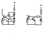
darkfenriz said:How about these two?
Both are ANF current sources with improved PSRR due to zener regulation, with the first possessing enhanced loop transmission and thus greater output impedance.
This of course is just as dependent on frequency as the forward path gain of the op amp used.
To my experience, incestuous CCS's like MikeB's #5 and #10 are very prone to oscillations and disappointing.
The circuit at the right of Darkfenriz's picture is one of the most dependable I know. It has a large bandwidth PSRR. For a temperature elevation of 50°C, the current will decrease about 20%. Using an LED instead of the current sensing transistor gives a better thermal compensation. Supplying the zener current with an other CCS is a quite unnecessary complication.
PSSR is not all. Rejection of the voltage variations at the CCS output may matter. A common base bipolar in a cascode configuration can be used to enhance it. However, once again, too much sophistication may give oscillations. My prefered scheme is to include a 1 Kohm resistor in series above the reference voltage and to connect the base of the common base ouput transistor to its other side. The 1 Kohm resistor has the double benefit of providing a sufficient voltage above the voltage reference and acting somewhat as a base stopper. Sometimes after I concluded that this simple scheme was really good, I found that Morgan Jones uses it in its valve amplifers.
More sophisticated circuits may give marginally better results but are less reliable.
forr said:The circuit at the right of Darkfenriz's picture is one of the most dependable I know. It has a large bandwidth PSRR.

Did you know that its output impedance is just as high as that of a cascode current source? 😎
forr said:For a temperature elevation of 50°C, the current will decrease about 20%.
This is a ''good thing'', for it enhances reliability.
- Status
- Not open for further replies.
- Home
- Amplifiers
- Solid State
- Searching the "best" CCS