Never tried. The LS7 is the same price too:
https://www.langrex.co.uk/products/ls7-cv1660-gec-nos-boxed-valves-tubes/
https://www.langrex.co.uk/products/ls7-cv1660-gec-nos-boxed-valves-tubes/
Higher mu DHTs are discussed in this recent thread over at AA, in which both Andy and I participated.
https://www.audioasylum.com/cgi/vt.mpl?f=tubes&m=286255
https://www.audioasylum.com/cgi/vt.mpl?f=tubes&m=286255
Problem with higher gain triodes like the 1B5/25S or the equivalent 1H6G is noise. I perfectly agree with @jhstewart9 on that. Even if they are well isolated they are still very prone to pick up all sorts of noises and vibrations. I have a bunch of them, they also measure very well but never found a way to use them.
I suspect this is a problem with most tubes that require less than 100 mA filament, typically 50-60mA.
I suspect this is a problem with most tubes that require less than 100 mA filament, typically 50-60mA.

My 30 to EL84 amp sounds great, but I need to rework it in order to further reduce microphonics. My first go at a microphonic reducing chassis set up was not successful. It is quiet enough with a very small number of the less microphonic tubes in my 30 stash, but you can’t just pop in a tube that measures well and go. It’s too bad these battery tubes are so microphonic because, other than that, the 30 into a trioded EL84 sounds great.Higher mu DHTs are discussed in this recent thread over at AA, in which both Andy and I participated.
https://www.audioasylum.com/cgi/vt.mpl?f=tubes&m=286255
I was thinking of something like this EL12n circuit but with 2P29L in filament bias as the first stage

My 30 to EL84 amp sounds great, but I need to rework it in order to further reduce microphonics. My first go at a microphonic reducing chassis set up was not successful. It is quiet enough with a very small number of the less microphonic tubes in my 30 stash, but you can’t just pop in a tube that measures well and go. It’s too bad these battery tubes are so microphonic because, other than that, the 30 into a trioded EL84 sounds great.
Rubber mounting alone probably isn't enough. But mass combined with rubber mounting is probably the best you can get. I've thought of taking a slab of 1.5 inch thick granite or marble, wet drill the socket holes in that with rubber under the saddles as well. Then have rubber feet under that slab as well. A 1.5 inch slab from your local kitchen granite store 17 inches x 12 inches would weigh about 31 pounds, 14 kgs. That much mass will not pick up vibrations easily. Whereas a hollow aluminum chassis is basically like mounting the tubes on a drum head! I gave up on that.
The freq response of the 124D & others in these curves is the bare bones result in the test cct.Is this bandwidth performance improved by the way it is used in your schematic?
When installed in a typical cct it may not perform as well. Loading of the secondary is very important.
I had used the H124D in the cct example since Andy recommended it on the basis of its core material.
But others of the series would work, when first looking at the IT choices available the H124E seemed OK.
🙂
Last edited:
The front end triodes really need something with a hi impedance in their cathode tail.I was thinking of something like this EL12n circuit but with 2P29L in filament bias as the first stage
That looks like a problem when biasing the way you have typically done that. Will be interesting to watch.👍
Besides vibration pickup thru the mounting these tubes probably need some ear muffs around theWhereas a hollow aluminum chassis is basically like mounting the tubes on a drum head! I gave up on that.
glass as well to prevent acoustic pickup thru the air. I thick Tiz did that on one of his a few years ago..
That set of curves looks almost contrived, to good to be real.As good is the LS7/CV1660. This is easier for to find for me. Price is not cheap but still acceptable.
The curves look like the same curve simply moved right by an equal interval by an automat!
😀
Rubber mounting alone probably isn't enough. But mass combined with rubber mounting is probably the best you can get. I've thought of taking a slab of 1.5 inch thick granite or marble, wet drill the socket holes in that with rubber under the saddles as well. Then have rubber feet under that slab as well. A 1.5 inch slab from your local kitchen granite store 17 inches x 12 inches would weigh about 31 pounds, 14 kgs. That much mass will not pick up vibrations easily. Whereas a hollow aluminum chassis is basically like mounting the tubes on a drum head! I gave up on that.
My experience with 30 tubes indicates that acoustic pickup through the air is significant enough to cause microphonics even if the both the tube socket mounting and the chassis are set up to damp vibration. The tube's envelope transfers enough vibration to the internals to be a problem. My thought is that the envelope needs to be isolated from acoustic energy in the room as well. Putting the 30 tubes in an enclosure is one way to do this. I have experimented with placing jars over 30 tubes, and this did help. Isolation mounting the socket within an enclosure that also isolates the tube from airbound vibration should allow for even overly microphonic tubes to be useable. Adding mass to the chassis and starving the filaments filaments should help as well.Besides vibration pickup thru the mounting these tubes probably need some ear muffs around the
glass as well to prevent acoustic pickup thru the air. I thick Tiz did that on one of his a few years ago..
Just to point out that you do not need to have center tap to split the phase. Just load the secondary with two equal value resistors to join them to ground to create a virtual center tap. All transformers have at least two wires on secondary and they are intrinsically nature's phase splitter. The only hitch is if you belong in the camp who doesn't like a loaded secondary then you need a center tap.
Last edited:
It's a short-tailed pair and, as John said, the cathode is not loaded high impedance enough to allow signal to pass to the inverted side to have a AC balance. You're better off with a 1:1 input transformer that allows you to create "doubling" of your SE design.I was thinking of something like this EL12n circuit but with 2P29L in filament bias as the first stage
View attachment 1160266
Likely they are model curves. I found them in the net as datasheets for this tube are scarce and those one can find don't have typical curves. But DHTs are more linear than anything else so any prediction won't be far off. It was more to get an idea of gain and possible operative conditions and voltage swing one can get.That set of curves looks almost contrived, to good to be real.
The curves look like the same curve simply moved right by an equal interval by an automat!
😀
I'm unfamiliar with PP design, since I've built SE for the last 12 years. I was thinking that if the DC balance was correct it would work. You're saying the AC balance would not work with the second grid grounded, and if that's the case I need a different setup.It's a short-tailed pair and, as John said, the cathode is not loaded high impedance enough to allow signal to pass to the inverted side to have a AC balance. You're better off with a 1:1 input transformer that allows you to create "doubling" of your SE design.
I'd forgotten about using a transformer with a pair of resistors for a virtual centre tap. I'll have to look at that. So in the EL12n schematic I posted the grid leaks for the EL12n are 560K. Would they double up as the 2 resistors after a transformer for a virtual centre tap? Come to think of it, could you do this with just a plate choke or not?
Ops, I have just realized that I should have multiplied by 2. Got confused with Philips datasheet which does not specify as usual. Normally drive is represented as g1-to-g1 while old Philips datasheet means per tube. With the EL34T for Class A PP, 24 V rms drive is per tube! So 1475+49 need 6Vrms input for 15W (400V, 10K plate-to-plate). It was too good to be true. The 1475 will do just fine but it needs a really good preamp. 🙄
Last edited:
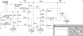
How about this for a basic design - filament bias 2P29L? I have 124b, also Lundahl LL1660/18mA, Lundahl LL1635/PP

My experience with 30 tubes indicates that acoustic pickup through the air is significant enough to cause microphonics even if the both the tube socket mounting and the chassis are set up to damp vibration. The tube's envelope transfers enough vibration to the internals to be a problem.
Good to know. That leaves headphone amps as projects to save for ones thin filament battery DHT tubes. Run the filaments on a power tool or RC car battery where you have a known safe recharger available. Three hours of headphones listening is a lot to endure anyway, making it a good battery project. While everyone's asleep the house is vibration free.
How about this for a basic design - filament bias 2P29L? I have 124b, also Lundahl LL1660/18mA, Lundahl LL1635/PP
View attachment 1160468
When I bought an IS transformer with CT from Jack Eliano to use as a phase splitter, he told me to always load the secondary. He described this method, put 100k across the secondary, measure distortion, try other values until the lowest distortion is obtained. Just relaying the message, I don't fully understand the implication of letting an IS just float or loading it. I do know that I blew out my function generator by testing phase splitting by sine wave and the scope with the secondary unloaded. At some point I must have disconnected a wire and caused a flyback pulse. And it was goodbye Rigol function generator for that channel.
- Home
- Amplifiers
- Tubes / Valves
- Schematic wanted for push-pull triode connected pentode amp with DHT front end