I haven't experience any buzz on my 100K TKD pot.Back to the SCG. I am getting some buzz on both channels with a 50k Alps pot at the 12-3 pm positions. It goes away below 12 pm and above 3 pm. What's the experience of others (@Alfi, @Vunce )who are using pots before the SCG? Getting any hum/buzz pickup at various pot positions? It could be the specific pot, but I want to ask before I dissemble it.

Thanks Vunce and Alfi! I’ll try NTC connection and see if it cures it. Or, it might be a faulty pot.
With R2 100k and R6 220 ohms there is virtually no Schade feedback and output impedance is very high, but good frequency response. Did the circuit you actually build have a higher value for R6 which would restrict bandwidth due to mosfet input capacitance? With output from the source the effective input capacitance is much lower so bandwidth would have been better.A little off topic, but thought George (@Tubelab_com) might be able to help me. I experimented with a power amp using the Schade method. Here's the schematic.
View attachment 1070781
I am getting very poor bandwidth at the top end. Probably not even making it to 10 kHz and quite a bit less than the sim. Getting good bit of gain. The device is an SCT10N120 with nice looking curves. It biases up exactly as shown. This is not an SCG topology, but it is identical to a Zen amplifier just with an SiC device. I even added 1000 ohms of source resistance to the input voltage generator, but the sim still shows very wide bandwidth.
The same device but with the inductor on the source and the output taken from the source pin sounds quite good. Okay, it is no VFET, but it sound like a decent class A amplifier. I pushed it to 1.5 amps and it was doing fine.
I made R1 into a 100k trimmer pot for easily changing the bias. It works nicely. The bias does wander a bit, but mostly stays close to where you set it. Certainly could be improved.
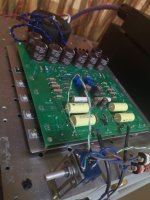
The inductor is the Hammond 193T. The chassis and setup was my choke-loaded VFET amp, but I pulled the VFETs for the OS2 amp and now using the setup for experimentation
The amount of feedback in this circuit is highly dependent on the impedance of the source that is driving the circuit.With R2 100k and R6 220 ohms there is virtually no Schade feedback.
This could be part, or all of the hum / buzz issue as with a pot at the input the fet sees a variable input impedance depending on the pot setting. This results in variable feedback and possible instability or oscillation at some pot positions. With the pot all the way down the gate sees 200 ohms to ground. With the pot all the way up the gate sees whatever the source impedance is paralleled with about 25K. With the pot at midrange the gate sees a minimum of 12.5K as the pot is essentially two 25 k resistors with one grounded and the other going to the source.
The 30 pF cap was an experiment to try on the simulator to see if it reduced the bandwidth as it's closer to what you have in your actual circuit. Adding more capacitance to the actual circuit would only reduce the HF response.
My early experiments with the UNSET circuit used vacuum tubes. The last iteration of my test board had a mosfet pair on each element of a pentode tube except the plate. I could apply a drive or feedback signal of either polarity with any DC offset to each element of the tube. I never found a foolproof method to apply the drive and the feedback to the same element, and some of this was due to the uncertainties of any input (source) accessible by the user. The simple pair of resistors applying feedback to the grid or gate while the drive is fed to the cathode or source (UNSET) worked the best as the two signals do not directly affect each other.
In a two (or more) stage amplifier where at least one stage inverts the signal there are more options for applying the feedback and signal.
I tend to use mosfets as followers in my designs as a follower is inherently linear. One can simply stack two N-fets on top of each other (cascode) and use one for feedback and the other for signal too. It works with triode tubes, but the overall gain is low. High Gm mosfets might do better.
Yes, you are absolutely right. The circuit I built did have 220R for R6. It looks like this works as a virtual earth amplifier, where the node between R6 and R2 is the virtual earth. R6 should be increased and R2 decreased, maybe like 5k and 50k combo might work given a source impedance of 500-600 ohms. Might need some experimentation. If you look at the first few Zen amplifier articles, Nelson uses 4.75K for R6.With R2 100k and R6 220 ohms there is virtually no Schade feedback and output impedance is very high, but good frequency response. Did the circuit you actually build have a higher value for R6 which would restrict bandwidth due to mosfet input capacitance? With output from the source the effective input capacitance is much lower so bandwidth would have been better.
But of course, all of this can be resolved with the SCG topology for a power amp.
George, the pot hum/buzz issue was with the preamp and not related to the power amp schematic I posted. Sorry if that was confusing.The amount of feedback in this circuit is highly dependent on the impedance of the source that is driving the circuit.
This could be part, or all of the hum / buzz issue as with a pot at the input the fet sees a variable input impedance depending on the pot setting. This results in variable feedback and possible instability or oscillation at some pot positions. With the pot all the way down the gate sees 200 ohms to ground. With the pot all the way up the gate sees whatever the source impedance is paralleled with about 25K. With the pot at midrange the gate sees a minimum of 12.5K as the pot is essentially two 25 k resistors with one grounded and the other going to the source.
Interesting about stacking two N-FETs. Cascode makes for pentode-y curves and maximizes gain, right? It was a way to make pentodes from triodes. So, I'm not sure how effective (elegant?) it would be as the one we are using where the bottom one is simply a follower and connects to the source of the gain FET.My early experiments with the UNSET circuit used vacuum tubes. The last iteration of my test board had a mosfet pair on each element of a pentode tube except the plate. I could apply a drive or feedback signal of either polarity with any DC offset to each element of the tube. I never found a foolproof method to apply the drive and the feedback to the same element, and some of this was due to the uncertainties of any input (source) accessible by the user. The simple pair of resistors applying feedback to the grid or gate while the drive is fed to the cathode or source (UNSET) worked the best as the two signals do not directly affect each other.
In a two (or more) stage amplifier where at least one stage inverts the signal there are more options for applying the feedback and signal.
I tend to use mosfets as followers in my designs as a follower is inherently linear. One can simply stack two N-fets on top of each other (cascode) and use one for feedback and the other for signal too. It works with triode tubes, but the overall gain is low. High Gm mosfets might do better.
the UNSET / FETSET uses a P-fet as a source follower to drive the cathode / source. It provides no gain, so there is only one gain device per stage, and the stage does not invert the signal. Stacking two N-fets allows for the possibility for two gain devices. I have not tried any of this with mosfets yet, only tubes. TV sets in the 60's used this concept for the RF gain stage in the tuner. Special tubes were developed for this purpose. See the simple schematic on page two of this data sheet. The Ecc2 terminal can be used for a feedback input.George, the pot hum/buzz issue was with the preamp and not related to the power amp schematic I posted. Sorry if that was confusing.
Interesting about stacking two N-FETs. Cascode makes for pentode-y curves and maximizes gain, right? It was a way to make pentodes from triodes. So, I'm not sure how effective (elegant?) it would be as the one we are using where the bottom one is simply a follower and connects to the source of the gain FET.
Attachments
The light finally came on. I see what you are suggesting now. In the cascode, you have a forth terminal to insert feedback, mostly independent of the signal input. Neat idea. I am still studying the curves in the spec sheet and thinking it over. The two tube triodes make for pentode-like curves, but what would happen with two FETs? Would be fun to investigate. With the curves on page 2, I am not seeing how a good amplifier could be made.
TV tuner tubes are typically variable Mu so that Automatic Gain Control can be applied. The cascode circuit shown was intended for a TV tuner where the overall gain was adjusted to keep the output signal in the range of minimum distortion through the entire RF / IF / demodulator signal chain.With the curves on page 2, I am not seeing how a good amplifier could be made.
I had a cascode circuit making stupid amounts of gain with a 12AX7 tube, but it was in a guitar amp. The THD in the stage was reasonable if I remember correctly, bit I never tried to optimize it. Eventually it got replaced with a gyrator loaded pentode for even more gain, over 60 dB which was limited by extreme microphonics.
Making progress on the updated PCB. The only thing I haven’t tested is the output buffer, but I am going to skip it and keep the simplicity. Performance is quite good and output impedance low enough to not worry about it. The only benefit might be better AC loading with a buffer, with the tradeoff being more components.
This circuit started out without an input cap.
If one would never remove an interconnect with the power amplifier and/or GCS powered is there a need for the GCS nput capacitor?
I know there is no DC coming out of my DSP box that will precede the GCS. Hate to buy an expensive capacitor for no good reason.
Scots are cheap - thrifty is a euphemism.
We could add a negative supply and maybe get rid of the input cap, possibly the output cap too with some combination of devices and operating points. But another supply is it’s own set of compromises. No free lunch.
Yesterday, I heard the Tokin 2sk2087c VFET in a choke-loaded source follower configuration and it was amazing. It has the bottom end of an F4 and the top end of the Sony. It felt like like I upgraded my speakers.
Will post the schematic later and maybe start it’s own thread. Need to figure out how to better control the bias. On one channel the bias runs away a bit too fast for my liking. I believe it is the gate current issue that Ben and ZM have referred to in other threads.
Will post the schematic later and maybe start it’s own thread. Need to figure out how to better control the bias. On one channel the bias runs away a bit too fast for my liking. I believe it is the gate current issue that Ben and ZM have referred to in other threads.
IMO, input/output caps are not the arch nemesis. The single rail psu works well here for simplicity and low parts count. Also, if the ground plain was separated between channels on the SCG pcb, this could be a dual mono psu with a single dual secondary trafo.
Last edited:
Can the SCG drive two feet of interconnect or should the circuit be placed as close to the amplifier input as possible?
My four amplifiers are separate and it is impossible to place a stereo board intimately close to two amplifiers. I may need four boards if that is necessary.
All of this is dependent on getting LAZY SINGING BUSH pcbs. Hope ZM makes them available.
My four amplifiers are separate and it is impossible to place a stereo board intimately close to two amplifiers. I may need four boards if that is necessary.
All of this is dependent on getting LAZY SINGING BUSH pcbs. Hope ZM makes them available.
My current interconnects are six feet long. Should be just fine. Output impedance is low and there is plenty of current for driving.
Sorry that my progress is slow. Life issues got in the way but I am getting there. Transformer reached me yesterday evening, installed and adjusted the parameters as suggested by ra7. I have also set the gain to 6X so that I have more flexibility in using it to drive my a few different amps. Currently still waiting for my actual chassis to be delivered while I mounted it on an aluminum plate to test. First impression is very positive. Warm, powerful sound. Will let it run for a few days before I listen critically.
Attachments

- Home
- Amplifiers
- Pass Labs
- Schade Common Gate (SCG) Preamp