
Strongly suggest keeping the chassis grounded to earth,
It was only going to be as a diagnostic test. But I changed my my mind and decided to restore the ground lift in the preamp.
Alas, I don’t have a 10K pot at the moment. Several 50K and 1 100K is all I got.
I am in no hurry, though. Maybe I’ll order one.
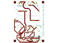
Attached are revised gerbers with the single-ended buffer. The footprint for the 4k7 resistor has been increased to allow for a bigger resistors to be used. Enjoy!
Attachments
Did the noise get resolved?Alas, I don’t have a 10K pot at the moment. Several 50K and 1 100K is all I got.
I am in no hurry, though. Maybe I’ll order one.
Another approach would be to put the pot after the preamp, something like a 1k-5k after the preamp would work if it is going into a high-impedance input. The buffer can drive this pot. This is a more ideal solution so that the signal is attenuated after increasing the gain and we're not throwing away signal when it is closer to the noise floor. See how P101 is configured here for example:
https://www.passdiy.com/project/preamplifiers/bride-of-zen
Did the noise get resolved?
I am still waiting for the new pot. I decided to delay further testing until then. My intuition says restoring the ground lift would have been enough, but I have not tried that.
I'll update.
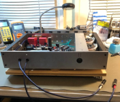
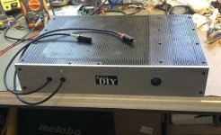
Almost ready to try in the system. I need to do a little work on the mono blocks first.
This chassis has housed multiple different projects which explains the unused holes there. It used to be a full featured preamp but at this time it's just a stripped down hot-rodded external amplifier front end only. Only one source and volume is controlled upstream. My output signal cabling exits through the front because the mono blocks live on the floor in front of the equipment shelf.
This chassis has housed multiple different projects which explains the unused holes there. It used to be a full featured preamp but at this time it's just a stripped down hot-rodded external amplifier front end only. Only one source and volume is controlled upstream. My output signal cabling exits through the front because the mono blocks live on the floor in front of the equipment shelf.
Attachments

Lovely! I operate it similarly, just with a volume pot. Curious about the monoblocks this will be driving.
from the HGF thread...
Excess hardware in the true diy spirit... where correct amount of kill is.... "over"..
Big CRC supply, rails ~27V. The onboard opamp is "just fine" of course, but we'll bypass that and feed it the DHT, I mean SCG instead..
Excess hardware in the true diy spirit... where correct amount of kill is.... "over"..
Big CRC supply, rails ~27V. The onboard opamp is "just fine" of course, but we'll bypass that and feed it the DHT, I mean SCG instead..
I owed everyone an update.
I received the 10K pot and installed it. Of course, the problem was not the pot, though, it was the tiny PC that was feeding the DAC that was feeding the preamp. Huge amount of noise. When I connected to the DAC directly using Bluetooth, it all went away and the noise floor dropped to pure black.
Or so I thought...it turns out that after 30 minutes of play time or so, a very faint puttering noise returns and that one does come from the preamp. By now, that puttering sound is familiar, it's the same puttering sound I heard before when the Zener string was underfed, but much sparser and much lower.
I am using a single transformer and single supply board in that build; I really thought it would be enough for the current demands, but it seems something may be drifting over time and some thermal noise returns.
So...I am back to studying @william2001 magic tricks, J112 + 220R R6 and Garden of Babylon 6.2V Zener X 12. But I am quite clueless and that may take some time. This project keeps on teaching, thanks Rahul!
Oh, it is the HGF. That should be a deadly combination. I predict sonic blissfrom the HGF thread...
Excess hardware in the true diy spirit... where correct amount of kill is.... "over"..
Big CRC supply, rails ~27V. The onboard opamp is "just fine" of course, but we'll bypass that and feed it the DHT, I mean SCG instead..

@ElArte check the connections and solder joints. That can cause a puttering noise sometimes as things warm up. I am constantly tinkering and sometimes forget to tighten the PS connector and the in/out connectors.
ElArte - don't get too sidetracked with my changes as far as "fixing" anything. The original circuit is fine as designed. I don't see any issue with using a single supply, the SCG is a light load.
OK, under microscope, I couldn’t identify any cold joint or bad contact. Wiring at terminal blocks was also reliable.
I still reflowed some joints with flux. Cleaned up the board and put it back in.
And that puttering noise was…WORSE!!!
Today, line level was higher than last time.
That got me thinking…I dialed the Vds on preamp boards to 30V from 35V for both channels…and that was like a magic volume knob for that puttering noise. At 30V, there’s no noise at all!
My test set up for this is drastic: The output of the preamp is connected to a THX (extremely low noise) amp, and I have high-sensitivity headphones connected to that THX amp. I don’t have any source connected to the preamp. So, I am listening for the preamp self-noise.
My suspicion was on the supply board, but the noise was from the preamp board.
So, it seems, at 69.5V of supply voltage, it seems my part can only handle ~30V of Vds.
Which is entirely fine for me. I am glad I got that figured out.
Last couple of pics after a few revisions / corrections. Both channels quiet now on my Sennheiser headphones. This was just for testing purposes, my SCG will only feed the HGF output stage in use. Had noise initially, and accidentally damaged the amp during the fault finding / testing process. Waiting on parts... With no volume pot, I moved R101 and R110 up to the RCA jacks (some nice MANLEY's), and those values are 1K and 10K respectively. Both input grounds bonded together (kinda obvious) to avoid any cross channel ground loops. The ceramic disc cap (.01uF) shunts unwanted RF to chassis ground.
Attachments

Good going!
I still have some degree of low and sparse puttering after several hours of being powered. I now suspect I may have degraded the JFETs when I erroneously had way too much current go through them.
I know it’s not the circuit as my headphones build is completely quiet always.
It’ll be a project for next winter!
I also had a strange issue where putting the top lid on caused some additional noise. Added a thick ground wire from the top lid to start ground and that seems to have fixed it. Those multi-panel powder-coated chassis may not be ideal for audio.
Yes, you got it: next step would be replacing the JFETs if there was too much current. They are tough little critters though.
I have always wondered about the powder coating. I would imagine the screws binding one panel to another keep them in electrical contact but have never tested it.
William, build is looking nice. I like the idea of a shunt cap for shunting RF to ground. I am playing with Laterals and they seem to be very finicky about bandwidth. Slowing them down helps.
I have always wondered about the powder coating. I would imagine the screws binding one panel to another keep them in electrical contact but have never tested it.
That’s the strange thing here. Using metallic screws caused noise. Using nylon screws didn’t. Very strange.
It’s also possible that I assigned side effects of degraded JFETs to circumstances that are not related. It all seems to work in mysterious ways sometimes.
It all seems to work in mysterious ways sometimes
Truer words never spoken 😅
I had a ground loop hum issue in my living room for over a year. Went to the ends of the earth making changes to the amp and preamp and grounding schemes to chase it down.
Long time after I gave up and stopped trying, I did a Google search and found some article on an A/V oriented website suggesting a ground loop breaker for your cable TV cable. Got one, installed it, problem solved. Dead quiet now.
Had to back ALL the way away from the problem to see it. (it was happening on all my sources with or without the TV or cable box being powered on)
Anyhow good luck chasing the noise gremlins!
HiAttached are revised gerbers with the single-ended buffer.
What is the Voltage value of power supply?
And how much current device is consuming?
🙂
Thanks
@ra7 @Tubelab_com
I've done some positive tests on a small scale to approach a mosfet (but can be applied to pentodes too) single-stage single-ended inductor-loaded power amp capable of 30W from 850 mVrms at its input . It's an evolution of the UNSET/FETSET concept by keeping the original gain of the stage while improving distortion and damping.
Can I ask your help to choose the right power mosfets, dissipation, layout, etc on a dedicated thread?
By now I've chosen IXTH20N50D and IRF9540 running around 2,4 A and 30V loaded by a 500mH inductor and decoupled by two 2.2mF and 1uF film.
Thanks in advance,
Roberto
- Home
- Amplifiers
- Pass Labs
- Schade Common Gate (SCG) Preamp