I have a pair of toroids with dual 32V secondaries, so I just plan to put the secondaries in series, like papa shows in the BZLS article.
Thanks again for sharing your knowledge.
Are you suggesting I should use a 2 X 35V in series for 70V and a single supply board?
Sure, the series connected secondaries work just fine. I will go full dual mono with my own project, but that's certainly not required or necessary, builder's choice.
The irascible ZM would say secondaries should be either wired in series or given separate rectifiers.
Curious about the J175 "problem". Is it the input one or the one in the buffer that is concerning you, Rahul?
With the lowered voltages does the 2SJ74 become more attractive?
I saw this device mentioned in a thread: UJ3N065080K3S
Could this make for a good brute force buffer instead of the J113/J175 combo?
Certainly not cheap and the fellow who was writing about it never got around to saying what it sounded like in his circuit. Looks like a super DN2540 to my, at best, dilettante's knowledge.
The irascible ZM would say secondaries should be either wired in series or given separate rectifiers.
I am a big fan of ZM, Rahul, Papa...
Rahul is the young padawan we all love.
ZM gets my movie references and is full of hard-earned knowledge. I hope to give him a hug one day.
Papa is the North Star.
Yes, secondaries should be either wired in series or given separate rectifiers. I agree.
This story is kinda complex because I made it complex and because all the parts don't agree with each other.
The mind likes the idea of dual-mono designs. One PSU supplies one amp/preamp PCB.
Alas, most modern DACs connect the signal ground of L/R channels (and on to protective earth), so it's dual mono until you get to the DAC and then things open the door to nastiness.
In the scenario I am currently solving for, I have four PCBs: 2 PSU PCBs, 1 preamp PCB and 1 headphones buffer PCB
As we all know, more PCBs = more fun...or does it?
This arrangement gives "silence":
In this arrangement, one PSU PCB supplies the left channel of the preamp/headphones buffer PCBs and one PSU PCB supplies the right channel of the preamp/headphones buffer PCBs.
This diagram doesn't show signal wiring because it is busy enough already.
This arrangement gives noise when the preamp PCB is connected to the DAC via RCA cables and a lot more noise when the preamp PCB is NOT connected to the DAC:
In this arrangement, the loads on PSU 1 and 2 are quite different. And the most direct common reference for both PSUs is via the DAC when the RCA cables are connected or via the ground-lifted Common Ground Point when the DAC is not connected.
You will note that in both arrangements, each secondary gets its own PSU with its own rectifier.
I am sorry, Rick, you never asked for all this, but I am working on understanding this stuff deeply, so I might as well share.
Curious about the J175 "problem". Is it the input one or the one in the buffer that is concerning you, Rahul?
In the second arrangement above, I assumed the noise is due to the fact there isn't a low impedance path between the two PSU grounds, and/or the fact that PSUs are at significantly different ground potentials.
In the second arrangement, the preamp board receives 15V more (because it draws much less current and therefore incurs much less drop at the level of PSU 1). I have not verified if that increased voltage contributes to the noise.
The J175 "problem" Rahul reported, I think, is related to the gain stage and the fact that "modern" J175s may not behave as nicely when pushed.
Rahul will confirm or deny.
With the lowered voltages does the 2SJ74 become more attractive?
I saw this device mentioned in a thread: UJ3N065080K3S
Could this make for a good brute force buffer instead of the J113/J175 combo?
Certainly not cheap and the fellow who was writing about it never got around to saying what it sounded like in his circuit. Looks like a super DN2540 to my, at best, dilettante's knowledge.
Not entirely related to these questions, but I think Rahul is still sorting this out.
The transformer situation is tricky if you want 2 PSU boards powered by 2 secondaries of 1 transformer. Right now, I honestly think it would be easier to use a single PSU with a 2 X 35V secondaries wired in series. Maybe the filtering on that single PSU would need to be beefed up for ultimate performance, but it would allow reaching the voltages Rahul recommended.
Now, if modern J175s give more THD when driven at higher voltages, then it's another story.
My application is quite a bit more complicated than the essential preamp use case, so it's self-inflicted learning.
El Arte - there is no question your situation is very different than mine. I do not ground any of my gear to the third pin. I am told I am living dangerously but most of my gear is not in metal boxes so I am not sure what I would ground with and to.
I have found this makes for a quieter system but not always - but that is usually due to something other than grounding.
What I see makes sense. I would use a separate power supply for each SCG board.
I have to use four DACs in my my system. Two of them use one channel RCA out and the other channel XLR out. I have had noise problems doing that. These are TOPPING D90 dacs which is all I can afford. But this might be similar to what you are experiencing. On one channel, when using a CINEMAG transformer from DAC to SCG one channel required the ground (pin 1) wire to be connected for lowest noise and the other channel required it be left unconnected. I am sure there is sense there as to why this is but i could not explain it.
I am not longer using the transformers and instead a PASS FE stage at one half gain and if memory serves the channel needing Pin 1 ground switched!
As you are doing - when the system becomes complicated you just have to try everything until you find what works.
My left channel, which is yet to be brought up to PCB status makes noise - the right side, with my old perf board and the new PCBs is silent.
I am hoping when I install the new PCB version the noise will go away but it might not.
As Roseann Roseannadana said: There is always something.
I know I have offered nothing of use! I thought if I kept typing something good would arise.
What I see makes sense. I would use a separate power supply for each SCG board.
Ah, I use the board with the 2 channels on it, but it makes no difference.
For the preamp build, I will definitely use one supply per channel. The supply board Rahul made is perfectly fine in that scenario because the current draw is so low.
It's the headphones amp build that troubles me. Even though I use the preamp board that has 2 channels on it, the headphones buffer board adds 1 more board, which is in fact 2 completely separated channel circuits. Opening the door for potential differences and current loops. I think a single supply for the headphones build will solve many problems. That R25 might do the trick.
These are TOPPING D90 dacs which is all I can afford. But this might be similar to what you are experiencing.
Yes, Topping here too and they do connect RCA L- and R- to earth ground. So, dual mono really stops there.
But since you float your preamp, I guess it doesn't matter to you.
As you are doing - when the system becomes complicated you just have to try everything until you find what works.
I always get it to work well eventually, but it's always a journey, even though each time I tell myself "I get grounding now!".
My left channel, which is yet to be brought up to PCB status makes noise - the right side, with my old perf board and the new PCBs is silent.
I can't tell you why, but I learned another reason that causes noise. Approaching resistor ratings without care! When I gave the headphones buffer its own supply, I didn't pay attention: The headphones buffer was then biased at 75 mA per channel...for a total 0.15 A and 0.7425 W of dissipation at the balancing resistors on the supply board, while those were rated 1/2 W >>> noise. I guess they would have burned out eventually, but it only took me a few seconds to detect the noise, so drama avoided.
There is always something.
Lord, isn't that TRUE!?
I know I have offered nothing of use! I thought if I kept typing something good would arise.
Eheh, all good, it helps to share the journey.
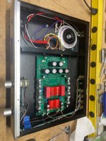
Need some help. I bought a pre-built SCG and donut from swap meet over a year ago and I finally got the opportunity to drop it into a chassis that had the inputs/output, selector, and pot installed. I'm using an Antek donut with 120VAC into the preamp PCB.
Board should be the original revision. There are jumper wires installed across the 1uF Wima bypass caps on the bottom. I don't see any notes on this bypass in the schematic.
Checkout procedure:
Test 1 - Regulator - 128V on both channels at R107/207 = OK
Test 2 - CCS Current. Ground Rlim with cliplead. Measure across R107/207 (1R) and adjust. 30mA = 30mV = OK
Test 3 - Set Q102 operating point. TP2 to GND = 11.8V (Target 20-30V) Adjustment of pot = no change. NOT OK
Test 4 - Set Q101 operating point. TP1 to GND = ~125V (Target 65V) = NOT OK
What's the jumper for? Should I pull the jumper? Should I pull semis and test them? Other thoughts / ideas?
Attachments

@rhthatcher please refer to this post of modification - https://www.diyaudio.com/community/threads/schade-common-gate-scg-preamp.380487/post-7441704

@manniraj - perfect.
I pulled the Wimas and jumper, turned R103/203 to get 0v (1mV - close enough?)
Reinstalled jumper.
Tp2 is 4.2 and 4.25v. Target ~4V. Good
Tp1 is 84.1 and 85.8v. Target ~85V. Good.
Next I need to set up an LED for the faceplate and then give it a listen.
I pulled the Wimas and jumper, turned R103/203 to get 0v (1mV - close enough?)
Reinstalled jumper.
Tp2 is 4.2 and 4.25v. Target ~4V. Good
Tp1 is 84.1 and 85.8v. Target ~85V. Good.
Next I need to set up an LED for the faceplate and then give it a listen.
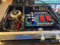
Cyan LED installed.
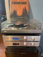
Time to give this a run with Pearl3, Aleph 30 monos, and Tannoys.
Jamming some French Canadian hard rock by Tonnerre. Sound is great!
Time to give this a run with Pearl3, Aleph 30 monos, and Tannoys.
Jamming some French Canadian hard rock by Tonnerre. Sound is great!
Attachments
Last edited:
Rahul - great design! I've had this in a box for over a year waiting to do the project. I found a little time today to tinker at the bench and knocked it out.
Next question. My other preamp in this system is a buffer, so zero dB gain. This SCG is set up for 10x/20dB gain. My "gain chain" is now really hot with the added 20dB gain. I get 3-4 clicks from minimum on my stepped attenuator to get to normal listening levels. I'm tempted to back it down to 11 or 13dB gain to get some more usable clicks on the attenuator.
If I want to lower gain by changing Rg to 3k or 4k, do I have to go back and pull the jumper, adjust RV103/203, etc? Or is it as simple as changing out Rg?
Nice build @rhthatcher and I forgot about my build of this preamp and that you had got it from me 🙂
Great to see its back into play.
By the way whats that "VFET Preamp" below the SCG interesting please share the details 😉
Great to see its back into play.
By the way whats that "VFET Preamp" below the SCG interesting please share the details 😉
It’s a 2SK79 buffer by @codyt with Slagle autoformer volume control.
I'm currently running a 2sk79 with a mu output from a Pimm self bias ccs. Looking at some alternatives I think I can run a ccs loaded stage from as little as 40v biased with about 20v on the output but I would like to use a b1 on the output instead of a mu output. The ccs I am thinking of using has a 5v minimum so that should leave plenty of swing for a pre. I think I have three main questions.
How can I modify the b1 to work in this situation? Is the cascode ZenMod suggested the way to go? Are there any existing schematics I can refer to?
Is there a better choice for an output...
How can I modify the b1 to work in this situation? Is the cascode ZenMod suggested the way to go? Are there any existing schematics I can refer to?
Is there a better choice for an output...
- vanofmonks
- Replies: 52
- Forum: Pass Labs
Yes, increase Rg and then adjust RV103 to get back to the targets. That should do it.If I want to lower gain by changing Rg to 3k or 4k, do I have to go back and pull the jumper, adjust RV103/203, etc? Or is it as simple as changing out Rg?
Edit: Looking back at the instructions, it seems you don’t need to turn RV103, if you have adjusted it for zero V already. Reducing Rg will bring down the Vd (gain x 8), which should be fine.
Last edited:
On second thought- will it drive an F4? Seriously- this might be the audio gods telling me it’s time to build an F4. I have some boards, and probably everything else is in the parts bin.
Check if you have that cap in your build:

Sorry, I may have misread the stage of evolution your build is in.
Sorry, I may have misread the stage of evolution your build is in.
It very much drives the F4, and in fact, that’s the intended application.On second thought- will it drive an F4? Seriously- this might be the audio gods telling me it’s time to build an F4. I have some boards, and probably everything else is in the parts bin.
- Home
- Amplifiers
- Pass Labs
- Schade Common Gate (SCG) Preamp