Got my PCBs yesterday.
Before I get to work - the 1R resistor - R102 - I assume you have decided you want it there! Is this for measurement purposes or do you think it makes the circuit sound better? I ask because I have tried the circuit both ways and I cannot hear any difference. My curiosity has the best of me.
Is it used to measure the current through the circuit?
Thanks, Rahul
Yup, that’s it: to measure current through the circuit. The 10R CCS resistor could also serve that function, but it includes the current flowing through Schade network. The 1R shows current flowing through only the gain device.
Here is a pic as promised. It is the RMIE version with Wima DC link cap for C102 and Wima FKP-4 for C101. Both channels powered by the same supply. I am very pleased with the new supply and regulator. Will post that soon.
I used parts at hand, and I was running out of some of them. The most sensitive parts are the coupling caps. I found the differences were huge.
Note the orientation of Q101 🪽
🪽

Here is a pic as promised. It is the RMIE version with Wima DC link cap for C102 and Wima FKP-4 for C101. Both channels powered by the same supply. I am very pleased with the new supply and regulator. Will post that soon.
I used parts at hand, and I was running out of some of them. The most sensitive parts are the coupling caps. I found the differences were huge.
Note the orientation of Q101
🪽
🤤
Please send me the Gerber for the power supply and I'll put in my combo board order in!!! The anticipation is hurting me.
Please send me the Gerber for the power supply and I'll put in my combo board order in!!! The anticipation is hurting me.
Ughh! Sorry, I tested it and have a couple of changes to make.
Ughh! Sorry, I tested it and have a couple of changes to make.
Ahah, all good…I lied, it doesn’t really hurt. Take all the time you need.
Ughh! Sorry, I tested it and have a couple of changes to make.
Are you adding fuse holders? If you aren’t, don’t let me make your life more difficult! I was just curious.
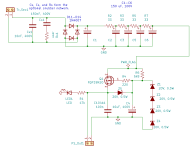
Here is the PS PCB. I wanted to make a few changes to the original, like making Vout adjustable, but such is life that I just cannot seem to find the time to do it. This one works and works great and most importantly, sounds great. So, here it is.
The neat thing in this one is the improved filter before the regulator FET. The combination of R+C filters and the number of filters gives us a very deep reduction in ripple. You don't need big caps either. This technique was given in Morgan Jones's book. I am very convinced of its effectiveness.
The FET is any ordinary N-Channel MOSFET that can do at least 100V drain-source. I am using the plastic STF3LN80K5, the plastic case requiring no isolator between the FET and the heatsink.
The transformer secondary should be about 50-65Vac depending on the target Vout. If shooting for 50V to the preamp, then feed 50-55Vac to the PS PCB. For higher voltages (SCG JFET pre max is 70V), use higher secondary voltages. The rectifier, filter, and regulator are all on the PCB. There is space for a snubber network that follows the Quasimodo technique explained expertly by our very own Mark J.
The output voltage is set by the zener string Z1-Z4. The output voltage Vout will be sum of zener string minus 4V. So, for a 50V output, you'd shoot for 54V with the zeners. For example, using three 18V zeners and shorting the fourth one. Zener voltages on the PCB are shown only as an example.
The input rectifier network uses the footprint of a TO-220 device. So, fancier ones are possible. C104b1 is optional. The 33 ohm resistors are 1/2W.
I think that's it. Schematic, BOM, and gerbers attached. Don't change the resistor/capacitor filter values--they go together.
Attachments
@ra7
I apologize for the timing, but as I begin planning the build, I need to ask:
Will the previous headphone buffer work well with this new version? My goals remain:
a) Lower the preamp's output impedance to provide a good damping factor for 32Ω headphones
b) Maintain the preamp's output signal (preserving transparency, headroom, and driving power)
I plan to power the headphone buffer using the same supply board, which would provide 50-55V instead of the previous ~100V.
I can alway add the headphone buffer later.
Rahul,
Do you find you like the circuit better with R102 in? Can one leave it out or is it benign?
Do you find you like the circuit better with R102 in? Can one leave it out or is it benign?
I made a Mouser project for the Power Supply: https://www.mouser.com/ProjectManager/ProjectDetail.aspx?AccessID=e3bed74f75
That is what I ordered just now. There could be mistakes in it, but, of course, I hope not.
Notes:
Please,
If you see any errors, report them and I will correct the project.
I will also make a Mouser project for the SCG board itself and I will share the link here.
That is what I ordered just now. There could be mistakes in it, but, of course, I hope not.
Notes:
- Does not include transformer
- Does not include parts for snubber network
- Assumes ~50V output (4 X 18V Zener diodes)
- Includes a heat sink for the MOSFET
- Does not use the cheapest parts
Please,
If you see any errors, report them and I will correct the project.
I will also make a Mouser project for the SCG board itself and I will share the link here.
No apology needed!@ra7
I apologize for the timing, but as I begin planning the build, I need to ask:
Will the previous headphone buffer work well with this new version? My goals remain:
a) Lower the preamp's output impedance to provide a good damping factor for 32Ω headphones
b) Maintain the preamp's output signal (preserving transparency, headroom, and driving power)
I plan to power the headphone buffer using the same supply board, which would provide 50-55V instead of the previous ~100V.
I can alway add the headphone buffer later.
Yes, the previous headphone buffer will work great hooked up to the output of this one. You might use the three pin jumper to try it with and without the output jfet buffer. 55-60V for headphone buffer sounds fine.
Rick, the 1R can be dropped without problems. It won’t affect the sound either way.
Thanks so much El Arte. The PS cart looks great. The only suggestion I might offer is that the rectifier footprint is for a TO-220 device. Something like this. But a 1N4007 in the usual footprint like you have will also work.
And thank you for making an SCG cart! Both of these will be hugely appreciated by others. I know I like it when there is a Mouser cart. I will add it to the first post.
And thank you for making an SCG cart! Both of these will be hugely appreciated by others. I know I like it when there is a Mouser cart. I will add it to the first post.
The only suggestion I might offer is that the rectifier footprint is for a TO-220 device.
I updated the project with the TO-220 device, it'll match the silkscreen better.
Sorry for infiltrating this thread, but I am looking at the Tubelab UNSET architecture, which has similarities to this project, trying to find a P-channel MOSFET for the board. The recommended one FQPF9P25 is well and truly unavailable. There is another option that is discontinued, but Mouser may have a delivery next month: FQP3P50.
I am new to these new fangled devices, being a tube enthusiast. As I understand it, I am looking for a device that has a minimum Drain-Source Voltage VDSS (250VDC for the FQPFP25), a low Crss (27pF), and Gate Threshold Voltage max (5.0V).
Searching with those criteria I saw DMP45H4D9HJ3, is that a good substitute? It is just €0.5 for 10 on TME.eu, so seems to be too good to be true.
VDSS 450VDC, Crss 3.1pF, VGS(TH) 5V.
The manufacturer is Diodes Incorporated - is that a reasonable brand? I will need to a buy a few to accommodate the 'learning curve', so a cheaper source is preferred.
@OldHector take a look at the IRF9640 - George mentioned in another post that he has used those in the UNSET boards. It has a -200V Vds rather than -250, though. Rated for the same current as the FQPF9P25....
Not sure the relative importance of different properties, but this IRFI9634G has a -250V Vds but is rated for less continuous drain current... might be worth a look.
Others who are more experience than me might have better suggestions 🙂.
Not sure the relative importance of different properties, but this IRFI9634G has a -250V Vds but is rated for less continuous drain current... might be worth a look.
Others who are more experience than me might have better suggestions 🙂.
Diodes Inc is reliable as far as I know. The device you linked will work fine in the tube circuit. Also, the IRF9640 will work fine.
I will post a more detailed reply later about my findings with these types of FETs in the SCG and UNSET type circuits, which you might find interesting. But I have to run now…
I will post a more detailed reply later about my findings with these types of FETs in the SCG and UNSET type circuits, which you might find interesting. But I have to run now…
This won't be what you want, but I decided to tackle the most difficult BOM first...
https://www.mouser.com/ProjectManager/ProjectDetail.aspx?AccessID=03A3F2BF34
These are the parts for the headphones buffer.
Notes:
As before, if you find errors or possible improvements, report them here and I will update the project for the benefit of all.
https://www.mouser.com/ProjectManager/ProjectDetail.aspx?AccessID=03A3F2BF34
These are the parts for the headphones buffer.
Notes:
- True complementary MOSFETs, for audio or not, are now dodos, so had to resort to IRFP9240PBF/IRFP240PBF
- Using 1 ohm for source resistors
- Using 1/2W resistors, even though not necessary
- Using 13.5K instead of 9.1K for the resistor nearest the trimmer
- The project includes a set of pin receptacles, for the resistor nearest the trimmer and for source resistors; I have not used these receptacles before
- The heat sinks for the MOSFETs are tall; be warned...but stable bias requires beefy sinks
As before, if you find errors or possible improvements, report them here and I will update the project for the benefit of all.
Finally, SCG FET board (big) for 2 channels:
https://www.mouser.com/ProjectManager/ProjectDetail.aspx?AccessID=88772f98ad
Notes:
As before, if you find errors or possible improvements, report them here and I will update the project for the benefit of all.
I will verify this project tomorrow. I have not ordered it yet.
https://www.mouser.com/ProjectManager/ProjectDetail.aspx?AccessID=88772f98ad
Notes:
- No JFETs...there is a bit of careful hunting to do for those
- Verify these are the WIMA you like
- Silly things like terminal blocks and headers are more expensive than smart device
As before, if you find errors or possible improvements, report them here and I will update the project for the benefit of all.
I will verify this project tomorrow. I have not ordered it yet.
- Home
- Amplifiers
- Pass Labs
- Schade Common Gate (SCG) Preamp