
I have wondered why the wires on resistors, which actually conduct dc current, are thinner than those of capacitor, which only charge and discharge, but no dc.That makes good sense. 1.2 mm is approx 18 gauge. Film cap clippings would make for a more sturdy post. I would worry resistor clippings would bend too easily.
Not to mention, most of the wire is cut off.
Last edited:
Hi
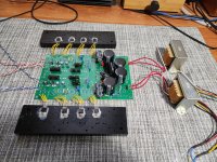
I couldn’t find any info in the BOM for the small heatsinks.
Could someone please post a picture so I know which transistors needs one and how big they must be. Please use Q11, Q101, 102, 103 instead of the role the transistors does in the circuit, ex CCS... Thanks
I need to info to order them and to also verify if a 1U enclosure is tall enough.
Thanks
Eric
Hi Eric,
Will your transformer fit in a 1U chassis?
I used heatsinks on all transistors just to keep my OCD in check, Hehe!
Will your transformer fit in a 1U chassis?
I used heatsinks on all transistors just to keep my OCD in check, Hehe!
Here are some options:
https://www.mouser.com/ProductDetail/CUI-Devices/HSS-B20-053H-01?qs=u4fy/sgLU9OZsBRGvc7wjA==
https://www.mouser.com/ProductDetail/Aavid/513102B02500G?qs=7jyBjEprRBj7D1NOUbnPQA==
https://www.mouser.com/ProductDetail/Wakefield-Vette/230-75AB?qs=sGAEpiMZZMuIeULrOsCjA7db9eIbkzqAjmvsStjteUw=
Any of the above heatsinks will work and they are needed for all except Q102 and Q202.
If you take care with isolating the transistors, you can mount them to the bottom plate.
Updating the BOM right now. See attached.
Attachments

TP2 is for measuringthe source pin of the bottom FET to make sure it is functioning right. It should have Vg plus 3 or 4 V.
Glad to hear it is working! What is the bias current? It should be 30 mA.
Glad to hear it is working! What is the bias current? It should be 30 mA.
Hi
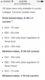
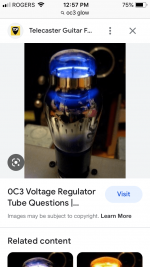
I believe each channel requires 105Vdc at 30mA to work in normal condition (could you please confirm this Rahul), well since this is DIY, I might replace the 3 Zeners with a OC3 tube voltage regulator which is coincidently rated for 105Vdc up to 40mA. I would need 1 per channel. I would put the OC3 on top of the enclosure, I believe it would look nice and the extra work and cost is minimal. See info below..
These don’t need 6.3V
Eric
Attachments
Eric, You don't have to worry about the circuit's current demand exceeding the tube's maximum current because the circuit's current flows through Q11. The zener string (or 0C3) combined with R12 set the gate voltage for Q11 which acts as a follower to regulate the supply voltage to the preamp circuit.
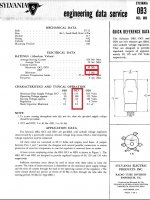
To substitute the 0C3 for the zener string, you need to satisfy the requirements of the 0C3. Note the 133V minimum plate voltage. Your power supply needs to provide that minimum, based on the lowest wall AC that you expect. Then you need to size the voltage dropping resistor, R12, for a minimum of 5mA to keep the tube turned on. Also note the maximum shunt capacitor value.
Important 0C3 numbers:
Attachments
- Home
- Amplifiers
- Pass Labs
- Schade Common Gate (SCG) Preamp