what should be a plan for a medium to large sound bar for 70" TV
2 sb20fr each for left and right for subwoofer bass duty what should be done
thinking of using a TPA 3255 amp
2 sb20fr each for left and right for subwoofer bass duty what should be done
thinking of using a TPA 3255 amp
Hello!! Could you please provide the filter values for this? Thank youI finally built my monster.
SB20 in a 30L aperiodic box with a LCR correction network in series with the driver.
What can I say, the transparency, timing, ambience is amazing.
Before that I had this driver in an OB with a 15" woofer, and it is great, but this, with all its shortcomings is just unreal.
Porcupine Tree, In Absentia, is a great test CD.

See post #715.Could you please provide the filter values for this?
Thank you, care to post box dimensions please? Is it heavely damped inside? Thanks
I finally got around to finishing my 1.5 way. After waffling on what veneer to use, I went with tissue paper, smh! It’s called decoupage and I’ve never done it before, but it was pretty easy, fast and inexpensive… It turned out pretty cool too if I do say so😎. It’s finished with a simi-gloss water based poly, but it’s hard to photograph. There’ll be an inset grill with green cloth and a short green stand eventually too.
They’re a touch brighter than I remembered though. I voiced them in a different space with a different amp and now I think it needs a bit more baffle step, ie bringing the FR down to match the sensitivity of the woofer. Right now it has a coil with a built in notch on the woofer and a parallel notch (in series) on the FR and that’s it. So no crossover per se and I’m wondering if I can just put a resister in series with the full range to pad it a bit? Maybe doubled up? I just need 1 ohm or less. Can I do that even though it’s run full range?
FYI, the tweeter on top is just a super tweeter that I was playing with when I designed it. I’ll use it, but for some reason I didn’t build it in.
@Freedom666
Thanks!
Ah, simplicity… if only I was that smart! I already adjusted the filter though. No series resistor, but the breakup needs some good correction for everything to sound natural and I added a zobel to the woofer to hit a true 1st order slope which controls its breakup region better too.
Thanks!
Ah, simplicity… if only I was that smart! I already adjusted the filter though. No series resistor, but the breakup needs some good correction for everything to sound natural and I added a zobel to the woofer to hit a true 1st order slope which controls its breakup region better too.
This has been long time coming, but I was overseas for a month and just came back.Hello!! Could you please provide the filter values for this? Thank you
To answer tortello, and many others who might have similar questions, check the attached file.
As for damping, it is not heavily dampened, felt on all internal walls and a bit of acousta-stuff kind of fluff in the volume. I started with a lot of fluff and slowly reduced it after extensive listening and adjusting. This thing can not be measured, you'll need to listen and decide what you like.
About measurements, I only do a few sweeps with Spectroid using Alan Parson's Sound Check CD. No REW, haven't got the time to muck around with mikes, cables, computers etc.
The only compulsory tests for me are the impedance ones as that'll tell me a lot about the system behaviour.
Very often people don't realise that every single resonance, being that from poorly placed dampening material, to mechanical issues with the driver(s), to bad interaction between xo and drivers will be reflected in the impedance curve.
Have fun
Attachments
Hi Stanislav!
Not being smart with baffle steps/ cross overs, how does your electrical circuit change the sound for box?
Not being smart with baffle steps/ cross overs, how does your electrical circuit change the sound for box?
Hi Johnny,
Not sure what you mean by "the sound for box".
Maybe you want to know what will the sound be without the circuit?
In that case the FR will be uneven, mids and highs will be pronounced, and bass subdued. The speaker will sound bright with not much bass and impact.
I personally am not aware of any single driver that can cover the whole spectrum evenly without similar circuit. It's simple physics.
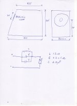
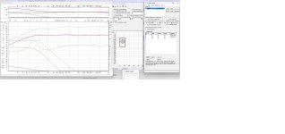
Have a look at the attached file which shows the simulation of the speaker in its box, QL = 3, with the parallel circuit in place. The simulation is done in Basta!
What you see is the L and R take care of the baffle step, and consequently lower the SPL, and the C raises the upper part of the freq. response to make it more or less flat.
I think you can simulate that in VituixCAD too.
Play with different values and observe the response. My values are not set in stone and slight variation may satisfy other tastes. I am currently using R = 3.9 ohm as that is what I had at the time, but listening tests told me that R should be higher, 4.7 - 5 ohm preferably.
Not sure what you mean by "the sound for box".
Maybe you want to know what will the sound be without the circuit?
In that case the FR will be uneven, mids and highs will be pronounced, and bass subdued. The speaker will sound bright with not much bass and impact.
I personally am not aware of any single driver that can cover the whole spectrum evenly without similar circuit. It's simple physics.
Have a look at the attached file which shows the simulation of the speaker in its box, QL = 3, with the parallel circuit in place. The simulation is done in Basta!
What you see is the L and R take care of the baffle step, and consequently lower the SPL, and the C raises the upper part of the freq. response to make it more or less flat.
I think you can simulate that in VituixCAD too.
Play with different values and observe the response. My values are not set in stone and slight variation may satisfy other tastes. I am currently using R = 3.9 ohm as that is what I had at the time, but listening tests told me that R should be higher, 4.7 - 5 ohm preferably.
Attachments
Is this a parallel LRC Stanislav? Or is it an LR plus a separate cap somewhere? Trying to understand how it does what you’re describing as I don’t really understand what the graphs are showing me. An LRC should just be providing a cut..
Well, yes, it is a parallel LRC, in series with the driver. And the interaction is not as simple as you described it.
The easiest to visualise it is to model it in Basta, varying values, or removing components to see what happens when you do that.
As I said before one is not obliged to use such circuit, but the result will be far from optimal.
The easiest to visualise it is to model it in Basta, varying values, or removing components to see what happens when you do that.
As I said before one is not obliged to use such circuit, but the result will be far from optimal.
I use a similar circuit in mine, but with the goal to basically just act as a cut centered around 5.5k since I have a .5 driver for baffle step compensation. I both modeled with measured data and measured to verify the results, so I do understand. I don’t remember my values exactly, but something like .2mh/6.8uf/6.8r… so quite different than yours. That’s why I don’t know exactly what yours does I’m sure. My biggest question is how the cap lifts the top as I could be interested in something like that.
Well, yes, it is a parallel LRC, in series with the driver. And the interaction is not as simple as you described it.
Hi, I'm a relative newbie. Please correct how I "simplistically" interpret this parallel LRC notch filter. I do these in my head using formulae (1st-order) HP f~(160khz/imp)/uF error half-pecent; LP f~(160hz*imp)/mH ditto; center f~5khz/sqrt(mH*uF) if imp locally flat and cancel out; -6dB/octave fall-off, -3dB at f point so vector-sums flat amplitude and phase if HP f=LP f (where phase offset 45+45=90° combined).
In the notch filter example, seen as LP and HP simultaneously connected each in series to the same driver acting as 2-way, LP f~(160hz*12ohm)/1.8mH~1067hz, HP f~(160khz/12ohm)/3.3uF~4khz, center~5khz/sqrt(6)~2040hz. Effects readily seen.
But then there are subtleties, as you say. Impedance is raised centered ~2khz forcing an otherwise deep notch, here back-filled by the 3rd-way parallel resistor R. What I don't quite get, is what happens to phase coherence in and around the notch!
(Just did a comp, offset 2-way 1st-order vs MEH 2nd-order Faital HF108/4FE35 with same notch filter to the CD; in Fullrange Photo Gallery.)
Last edited:
You really lost me there...
If you need theory check Vance Dickason's and David Weems' books, plenty of theoretical stuff.
For practical examples check Tony Gee's solo designs, some attached below.
Not really for SB20 but the principles are the same.
If you need theory check Vance Dickason's and David Weems' books, plenty of theoretical stuff.
For practical examples check Tony Gee's solo designs, some attached below.
Not really for SB20 but the principles are the same.
Attachments
Need Suggestions for a FullFrange system min 35Hz to 16kHz ( since I cant hear anything above 13K)
I have the following drivers SB20FRPC30 and for bass duty Eminence Lab 12 - 6Ohm , Peerless XLS 10
SB Audience BIANCO-18SW450 18" Subwoofer SB Audience Rosso-21SW800 21 subwoofer
miniSp 2x4HD and 4 channel Hypex amps
what configuration should I be doing. Music I listen is electronic techno and Pop Rock
I will also look at OB once I do this Box experience
regards
anand
- Home
- Loudspeakers
- Full Range
- SB Acoustics SB20FRPC30-8 (8" Fullrange Cheap Monster II)