Hi , yes I can , here are the files 😉
Regards,Alex
Hi Alex
Thanks for this all files,

Good you are back, Alex!
Every new pcb brings a smile to all of us! I always print it off in colour then walk to my local café for a careful examination with strong coffee........ always a pleasure.
Beautiful work, congratulations to our resident da Vinci........
Ciao,
Hugh
Thank you Hugh ,very much appreciated your comments 🙂 Enjoy, your strong coffee .😉
Regards, Alex
Hi Alex
Thanks for this all files,
You welcome ! 😉
Regards,Alex
i like your pcb art
Hi Alex
You PCB art is outstanding and I am really tempted to build a sara amp...
But I have two questions: What power supply did you use?
Second question: I know that I could use your pdf's to get the pcbs done, but your amazing silkscreen work deserves profesionally produced pcb's... as you keep your .lay files: is there a possibility to buy them ?
best regards
Christoph
Thanks you , well, power supply maximum at rail +/-55V acording to schematic . Check your PM box for details . 🙂
@Alex,
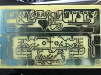
I printed PCB for your Amplifier
What is the maximum output power that can be obtained from this amplifier?
What should be the current for maximum power?
What should be the PCB copper thickness? (mine is with 1OZ copper)
What is the optimal bias current?
Here is my PCB.
I printed PCB for your Amplifier
What is the maximum output power that can be obtained from this amplifier?
What should be the current for maximum power?
What should be the PCB copper thickness? (mine is with 1OZ copper)
What is the optimal bias current?
Here is my PCB.
Attachments
1) 2x130w in 8ohm
2) 20 amper peak
3) 1oz=35um. It is ok but you can put a copper wire on the high currents PCB.
4) 0.3 A total bias current for all 3 transistors, or 0,1A for each final transistor.
2) 20 amper peak
3) 1oz=35um. It is ok but you can put a copper wire on the high currents PCB.
4) 0.3 A total bias current for all 3 transistors, or 0,1A for each final transistor.
@greierasul
Comparing other amplifier in different thread, output power seems less compared to complexity.
What are the main highlights of this amp, comparing to others (Eg: Apex)
I am just curious 🙂
Comparing other amplifier in different thread, output power seems less compared to complexity.
What are the main highlights of this amp, comparing to others (Eg: Apex)
I am just curious 🙂
Very good sound, very good stability, very good general performance, symmetric slew-rate, etc,etc... I do not want to speak about another amplifier. Every designer has own vision about the amplifiers. 😉 (call me Raimond, that's my name).
Thanks Raimond.
Do I need to use all resistors of 1% tolerance?
Also the schematics seems to be little different than PCB, or may be I am looking at the wrong combination.
What is the final schematics and PCB?
Regards,
Edison C.
Do I need to use all resistors of 1% tolerance?
Also the schematics seems to be little different than PCB, or may be I am looking at the wrong combination.
What is the final schematics and PCB?
Regards,
Edison C.
Not all resistors must be 1% tolerance. R1,R7,R8,R9,R10,R23,R16,R43,R18 are indicated to be with the tolerance of 1%. The rest of the resistors can be with 5%.
Tell me exactly what difference you mean.The wiring has been adapted to the requirements of reality, and there may have been small differences, but they do not matter in the economy of the scheme. Tell me exactly where you worry about it and explain it.
Regards,
Raimond
Tell me exactly what difference you mean.The wiring has been adapted to the requirements of reality, and there may have been small differences, but they do not matter in the economy of the scheme. Tell me exactly where you worry about it and explain it.
Regards,
Raimond
Hi Alex,
Can you increase spacing between output devices on your latest layout on post #78?
It will be very difficult to mount TO-264 device with current spacing.
Regards
Sonal Kunal.
Can you increase spacing between output devices on your latest layout on post #78?
It will be very difficult to mount TO-264 device with current spacing.
Regards
Sonal Kunal.

Hello,
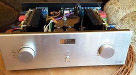
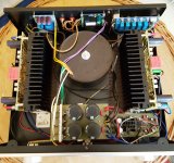
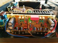
A very good sounding amplifier. Congratulations to Raimond.
Thanks also to Alex, for his support.
Regards
Gerd
A very good sounding amplifier. Congratulations to Raimond.
Thanks also to Alex, for his support.
Regards
Gerd
Attachments


- Home
- Amplifiers
- Solid State
- SARA-2016